Locking switch driving mechanism and multistage mechanical cooperation type passive intelligent lock

A switch-driven, intelligent lock technology, applied in non-mechanical transmission-operated locks, building locks, lock applications, etc., can solve problems such as power failure, short circuit, easily damaged locking structure, violent destruction or maintenance of intelligent locks, etc. , to achieve the effect of improving precise locking or unlocking, realizing precise locking and unlocking, and realizing precise regulation

Pending Publication Date: 2022-07-22
GUANGZHOU JINYUDA LOGISTICS CO LTD +1
View PDF0 Cites 0 Cited by
  • Summary
  • Abstract
  • Description
  • Claims
  • Application Information

AI Technical Summary

Problems solved by technology

With the development of science and technology, people consider the retrospective requirements of medical biological sample storage devices, and apply smart lock technology to medical biological sample incubators as a locking structure for the cover and cover of the incubator. However, traditional smart locks cannot be separated from the power supply. Drive, among them, traceability, identification, driving lock switch and other actions need to be realized by power-driven machinery or communication units. Active smart locks are easily limited by accidents such as power outages, short circuits, and faults, and there is greater instability. Once this instability occurs in the biological incubator, for example, if the circuit of the predestined intelligent lock in the incubator loaded with test samples fails, it needs violent destruction or maintenance to unlock it, and violent destruction will lead to traceability and identification functions Ineffective, and maintenance will take a long time, which will easily affect the quality of the test samples and seriously affect the insulation effect of the sample incubator. Therefore, the intelligent locking structure of the incubator in the prior art lacks practicability and needs to be improved urgently
[0003] At the same time, the traditional sample incubator locking structure generally includes a lock tongue and a hasp. The lock tongue is driven by the driving source and hooked into the buckle of the hasp when the limit cover is required. In this structure, the lock tongue It is directly connected with the buckle. When the buckle is dragged by the cover body, it will exert this force on the lock tongue. Over time, the lock tongue is prone to deformation. The traditional lock tongue is driven by the driving source and mostly moves along a straight line. Therefore, , the deformed lock tongue has a negative impact on the overall movement path of the lock tongue, which may easily cause the lock tongue to fail to disengage from the buckle, resulting in invalid unlocking, which seriously affects the use of the sample incubator, and needs to be improved urgently
[0004] Moreover, most of the driving sources adapted to the above-mentioned dead bolt and hasp are linear telescopic driving sources, and mechanical linear telescopic driving sources generally tend to overdrive, for example, when the driving dead bolt is inserted into the hasp When using the buckle, the stroke length of the output end of the general driving source is much longer than the moving path length of the lock tongue, so as to ensure that the drive source can drive the lock tongue to the preset buckle smoothly, which makes the lock tongue easy to impact the buckle. On the inner wall of the cavity, over time, it is easy to damage the locking structure and affect the use of smart locks, which needs to be improved urgently

Method used


Image

  • Locking switch driving mechanism and multistage mechanical cooperation type passive intelligent lock
  • Locking switch driving mechanism and multistage mechanical cooperation type passive intelligent lock
  • Locking switch driving mechanism and multistage mechanical cooperation type passive intelligent lock

Examples


Embodiment Construction

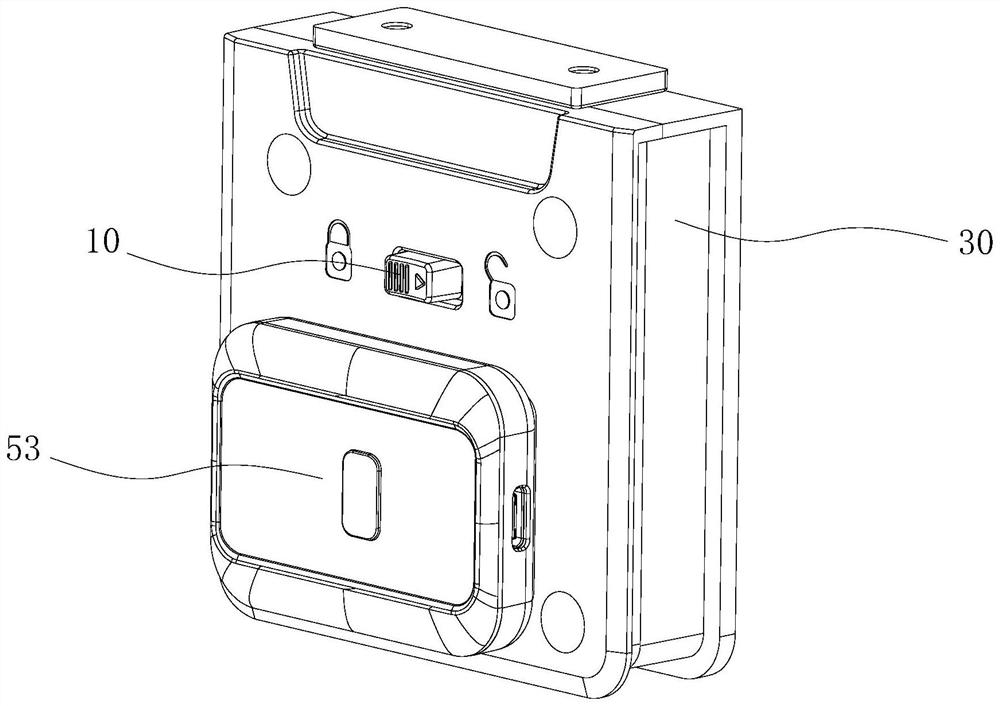
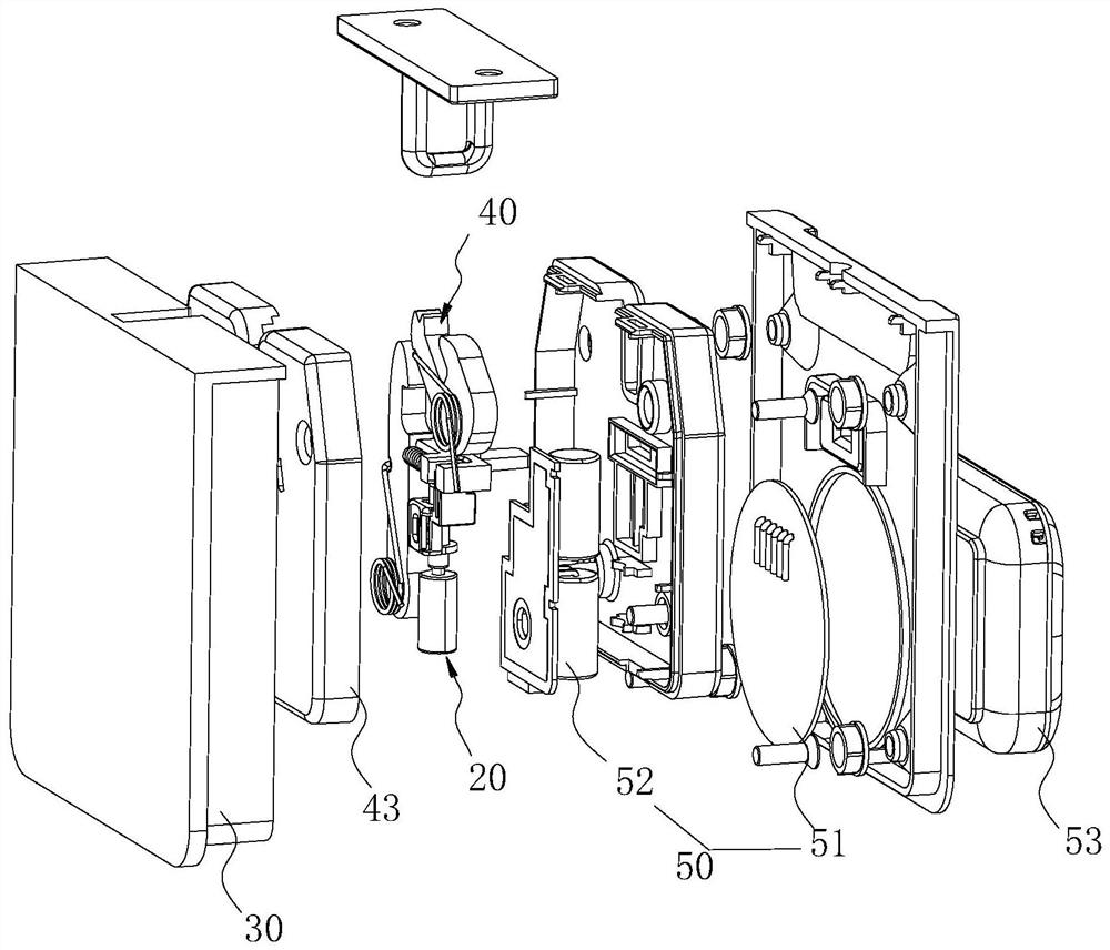
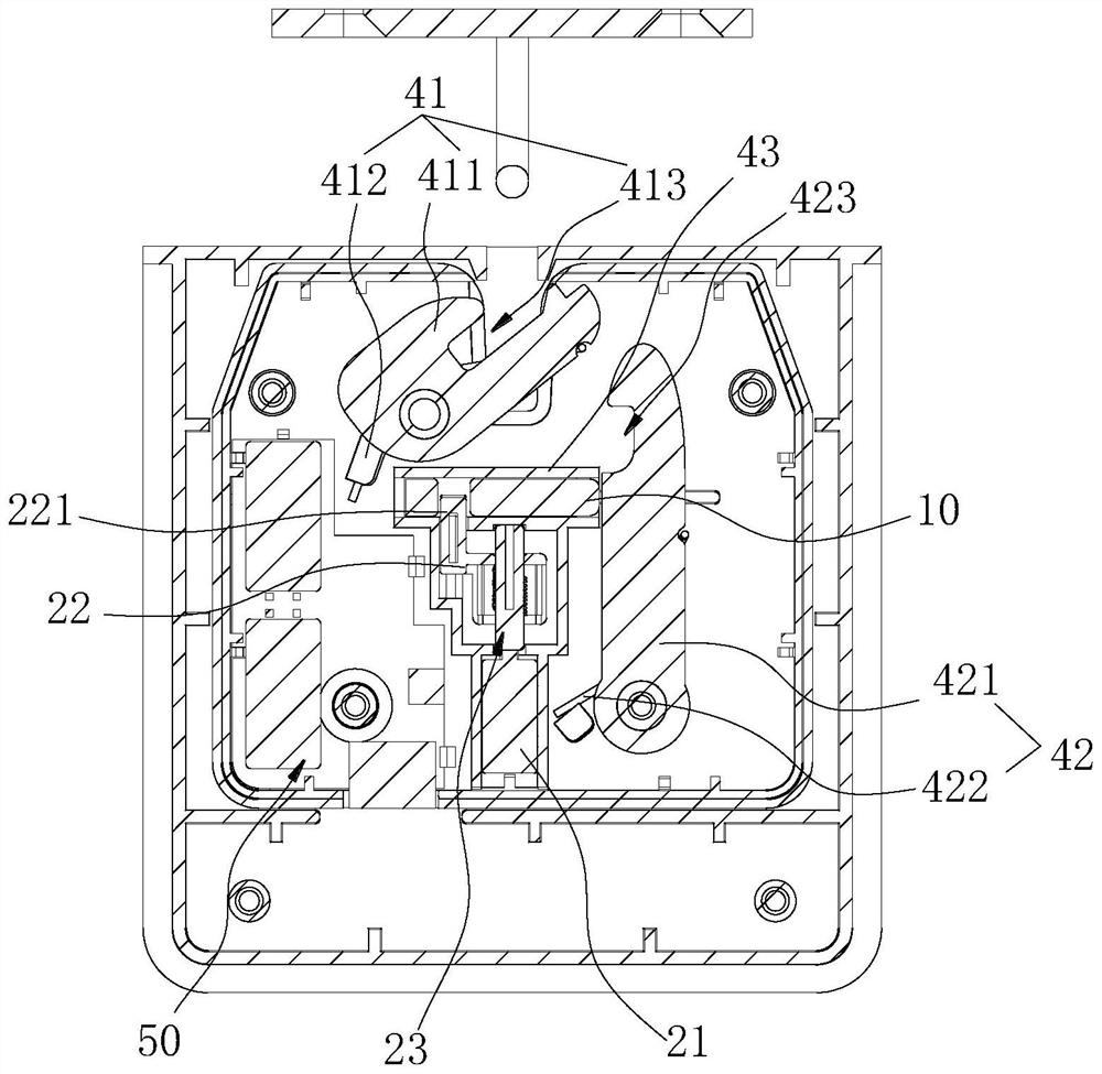
[0031] The following describes in detail the embodiments of the present invention, examples of which are illustrated in the accompanying drawings, wherein the same or similar reference numerals refer to the same or similar elements or elements having the same or similar functions throughout. Attached below by reference Figures 1 to 4 The described embodiments are exemplary and are intended to explain embodiments of the present invention and should not be construed to limit the present invention.

[0032] In the description of the embodiments of the present invention, it should be understood that the terms "length", "width", "upper", "lower", "front", "rear", "left", "right", "vertical" "," "horizontal", "top", "bottom", "inside", "outside", etc. indicate the orientation or positional relationship based on the orientation or positional relationship shown in the accompanying drawings, which are only for the convenience of describing the embodiments of the present invention and ...


PUM


Abstract

The invention belongs to the technical field of locking accessories, and particularly relates to a locking switch driving mechanism and a multistage mechanical matching type passive intelligent lock.The locking switch driving mechanism comprises a linear moving block and a servo driving assembly, and the servo driving assembly comprises a servo motor, a limiting moving frame and a transmission part; the transmission part is arranged at the output end of the servo motor, the limiting moving frame is arranged at the output end of the transmission part, and the limiting moving frame can be connected with the linear moving block in a clamped mode; the transmission component comprises a rotating shaft and a guide spring, the limiting moving frame is rotationally connected to the rotating shaft, a guide protruding block is arranged on the circumferential side wall of the rotating shaft, the rotating shaft is sleeved with the guide spring, the two ends of the guide spring abut against the limiting moving frame, and the guide protruding block is slidably connected with a threaded groove of the guide spring. A rotating shaft with a protruding block and a spring structure are adopted to simulate a lead screw transmission system, and the situation that the movement path of the switch is affected by deviation of the output end of a linear mechanical telescopic driving structure is avoided.

Description

technical field [0001] The invention belongs to the technical field of locking accessories, and in particular relates to a locking switch driving mechanism and a multi-stage mechanical matching type passive intelligent lock. Background technique [0002] The medical biological sample incubator is usually locked and sealed with a lock to prevent the biological sample from being stolen, lost, replaced and other incidents that can be opened by anyone at will because the medical biological sample incubator is unlocked during transportation. With the development of science and technology, people take into account the retrospective requirements of medical biological sample storage devices, and apply smart lock technology to medical biological sample incubators as a locking structure between the incubator cover and the cover body. However, traditional smart locks cannot be separated from the power supply. Drive, among them, traceability, identification, drive locking switch and oth...

Claims


Application Information

Patent Timeline
Patent Type & Authority Applications(China)
IPC IPC(8): E05B47/00E05B15/00E05B15/10E05B49/00
CPCE05B47/0012E05B15/00E05B15/10E05B49/00E05B2047/0018
Inventor 刘为敏周婕王洁桐周靖宇
Owner GUANGZHOU JINYUDA LOGISTICS CO LTD
Why Eureka
Try Eureka