Return air utilization device

A cylinder and air pipe technology, applied in the field of return air utilization devices, can solve problems such as affecting processing efficiency, and achieve the effects of improving production and processing efficiency, ingenious and simple design, and novel structure

Pending Publication Date: 2022-07-22
NINGBO GZX PV TECH
View PDF0 Cites 0 Cited by
  • Summary
  • Abstract
  • Description
  • Claims
  • Application Information

AI Technical Summary

Problems solved by technology

[0002] Photovoltaic products are processed on the tooling equipment, and then the workers put the products into the finished box, which affects the processing efficiency due to the large quantity

Method used


Image

  • Return air utilization device
  • Return air utilization device
  • Return air utilization device

Examples


Embodiment

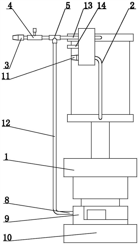
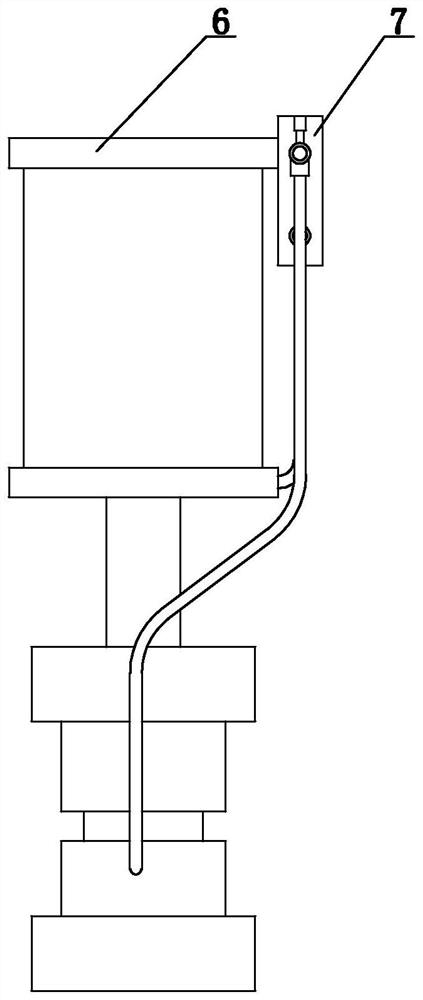
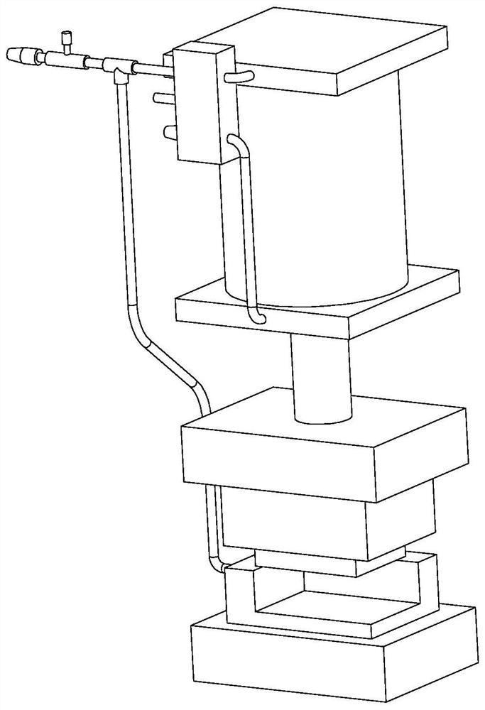
[0012] like figure 1 , 2 The air return utilization device shown in 3 and 3 includes a base, a tooling die 1, a cylinder 6 and an electromagnetic lock 7. The base 10 is provided with a workpiece seat 9, the workpiece seat 9 is provided with a tooling die 1, and the tooling die 1 is provided above. There is a cylinder 6, the upper side wall of the cylinder 6 is provided with a solenoid valve 7, the cylinder 2 is connected to the upper part of the solenoid valve 7 through the trachea a13, the trachea a13 is provided with a three-way joint 5, and the three-way joint 5 includes a port, b port and c port. a13 passes through the a port and the c port, the air pipe a13 on the a port side is connected to the throttle valve 4 and the muffler a11 in turn, the air pipe b12 on the b port side is connected to the air inlet of the workpiece seat 9, and the lower part of the solenoid valve 7 is provided with an air pipe c2. c2 is connected to cylinder 6.

[0013] The electromagnetic lock 7...


PUM


Abstract

The invention relates to the field of photovoltaic product tools, in particular to a return air utilization device. The return air utilization device comprises a base, a tool die, an air cylinder and an electromagnetic lock, a workpiece seat is arranged on the base, the tool die is arranged on the workpiece seat, the air cylinder is arranged above the tool die, an electromagnetic valve is arranged on the side wall of the upper portion of the air cylinder, the air cylinder is connected with the upper portion of the electromagnetic valve through an air pipe a, and a three-way connector is arranged on the air pipe a and comprises a port a, a port b and a port c. The air pipe a penetrates through the opening a and the opening c, the air pipe a on the opening a side is sequentially connected with the throttling valve and the silencer a, the air pipe b on the opening b side is connected with an air inlet of the workpiece base, and the air pipe c is arranged on the lower portion of the electromagnetic valve and connected with the air cylinder. The air cylinder has the beneficial effects that the structure is novel, the design is ingenious and simple, and return air exhausted when the air cylinder returns is used for the next process action for machining products or workpieces.

Description

technical field [0001] The invention relates to the field of photovoltaic product tooling, in particular to a return gas utilization device. Background technique [0002] Photovoltaic products are processed on tooling equipment, and then workers put the products into finished boxes. Due to the large number, the processing efficiency is affected. SUMMARY OF THE INVENTION [0003] In order to solve the above-mentioned technical problems affecting the processing efficiency, the present invention provides a return gas utilization device. [0004] The technical scheme of the present invention is as follows: [0005] The return air utilization device includes a base, a tooling die, a cylinder and an electromagnetic lock. The base is provided with a workpiece seat, the workpiece seat is provided with a tooling die, a cylinder is arranged above the tooling die, and a solenoid valve is arranged on the upper side wall of the cylinder. The upper part of the solenoid valve is connec...

Claims


Application Information

Patent Timeline
IPC IPC(8): F15B21/14H01L31/18
CPCF15B21/14H01L31/18F15B2211/88
Inventor 黄昊威
Owner NINGBO GZX PV TECH
Why Eureka
Try Eureka