
Slewing bearing and manufacturing method and application thereof

A technology for slewing bearings and manufacturing methods, which is applied to ball bearings, manufacturing tools, roller bearings, etc., can solve the problems of large slewing bearings and cumbersome installation processes, and achieve strength and firmness, simple installation process, and convenient installation The effect of arrangement

Pending Publication Date: 2022-07-22
永康市康中工贸有限公司
View PDF1 Cites 0 Cited by
  • Summary
  • Abstract
  • Description
  • Claims
  • Application Information

AI Technical Summary

Problems solved by technology

[0006] The purpose of the present invention is to provide a slewing bearing and its manufacturing method and application, which solves the shortcomings of the slewing bearing in the prior art, such as large volume and cumbersome installation process

Method used


Image

  • Slewing bearing and manufacturing method and application thereof
  • Slewing bearing and manufacturing method and application thereof
  • Slewing bearing and manufacturing method and application thereof

Examples


Embodiment 1

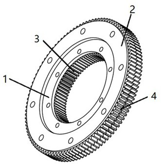
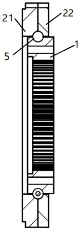
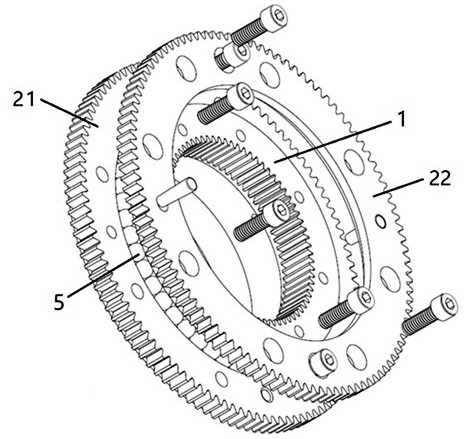
[0047] Example one, as image 3 As shown, when the rolling elements are balls 5, since the cross-section of the balls 5 is circular, correspondingly, the cross-sections of the annular grooves provided on the outer side of the inner ring gear 1 and the corresponding inner side of the outer ring gear 2 are both the same semicircle. In this way, when the inner ring gear 1 and the outer ring gear 2 are combined, the annular grooves of the two together form a circular raceway for accommodating the balls 5 .

[0048] Further, when the outer ring gear 2 is composed of the first outer ring gear 21 and the second outer gear 22, when processing the annular groove, the first outer gear 21 and the second outer gear 22 are firstly fastened with fasteners Fasten them together, and make an annular groove with the joint seam of the two as the center line to ensure that the annular groove of the outer ring gear 2 and the annular groove of the inner gear 1 can accurately form the raceway of th...

Embodiment 2

[0049] Embodiment 2, when the rolling body is the roller 6, the section of the roller 6 is a square, and, as Figure 5 As shown, in the technical field, the adjacent rollers 6 are generally arranged in opposite directions, so as Figure 4 As shown in the figure, the cross-sections of the annular grooves provided on the outside of the inner ring gear 1 and the corresponding inner side of the outer ring gear 2 are the same isosceles right angle. The annular grooves together form a square roller 6 raceway.

[0050] Further, when the outer ring gear 2 is composed of the first outer ring gear 21 and the second outer gear 22, when processing the annular groove, the first outer gear 21 and the second outer gear 22 are firstly fastened with fasteners Fasten them together, and make an annular groove with the joint seam of the two as the center line to ensure that the annular groove of the outer ring gear 2 and the annular groove of the inner gear 1 can accurately form the raceway of t...


PUM


Abstract

The invention relates to a slewing bearing and a manufacturing method and application thereof. The slewing bearing comprises an inner gear ring, an outer gear ring and a rolling body, first meshing teeth are arranged on the inner side of the inner gear ring, second meshing teeth are arranged on the outer side of the outer gear ring, and the outer gear ring comprises a first outer gear ring body and a second outer gear ring body which are fixedly connected. The manufacturing method of the slewing bearing comprises the following steps: processing one metal circular ring into the inner gear ring, and fastening the two metal circular rings together to be processed into the first outer gear ring and the second outer gear ring. The slewing bearing is applied to motion control of a workpiece clamping assembly in the polishing machine. According to the slewing bearing, the inner gear ring and the outer gear ring are directly connected through the rolling bodies, the size miniaturization of the slewing bearing with the inner teeth and the outer teeth is achieved, the strength of the slewing bearing is improved, and due to the design that the outer gear ring is divided into two parts, the slewing bearing is easier and more convenient to install.

Description

technical field [0001] The invention relates to the technical field of mechanical design, in particular to a slewing bearing, a manufacturing method thereof, and an application in a polishing machine. Background technique [0002] At present, the commonly used bearing with internal or external teeth in the mechanical field is a component called a slewing bearing in the industry. This component has extremely strong lateral bearing capacity and a compact design. It is an excellent mechanical component, but a single-tooth slewing bearing cannot simultaneously Realize different transmission functions, and the slewing bearing with internal teeth and external teeth at the same time can realize different transmission functions at the same time. [0003] Chinese utility model patent CN213711620U "A slewing bearing, a rotary lift mechanism and an AGV trolley" discloses a slewing bearing with both internal and external teeth, which includes a middle support ring and an inner gear ring...

Claims


Application Information

Patent Timeline
Patent Type & Authority Applications(China)
IPC IPC(8): F16C19/16F16C19/36F16C33/58F16H55/17B23P15/00B24B41/06B24B47/00B24B47/12B66F9/075
CPCF16C19/16F16C19/36F16C33/581F16H55/17B66F9/07504B24B41/062B24B47/12B24B47/00B23P15/00
Inventor 吕晓明陈江林
Owner 永康市康中工贸有限公司
Learn More