Telescopic VR head-mounted device and use method thereof

A head-mounted device and telescopic technology, applied in optical components, instruments, optics, etc., can solve problems such as inability to adjust, discomfort and impact on wearers, reduce the impact of equipment volume and quality, improve user experience, expand The effect of the overall volume

Pending Publication Date: 2022-07-22
贵州云墨科技有限公司
View PDF0 Cites 0 Cited by
  • Summary
  • Abstract
  • Description
  • Claims
  • Application Information

AI Technical Summary

Problems solved by technology

[0003] However, in the prior art, the existing VR head-mounted devices usually consist of two parts: the headband and the main body of the device. The specific size and size of the main body of the device have been determined during the production process and cannot be adjusted. People with different body types will have large differences in head size, so in the process of actual use, external light will enter the interior of the device, and some people will not be able to obtain a good experience. Therefore, VR headsets generally have By adjusting the size of the headband to make the main body of the device fit on the skin of the user's face, to achieve the effect of preventing external light from entering the device, but this method mainly achieves the purpose of size adjustment by controlling the tightness of the headband. The tighter the headband, the better the fitting effect. In actual operation, the excessive contraction of the headband will easily make the wearer feel uncomfortable, and after wearing it for a long time, it will lead to poor blood circulation in the face, which will easily affect the wearer. There are certain limitations, and the actual effect of this method is easily affected by the shape of the main body of the device. It can only be applied to some small VR headsets, and its effect on some larger VR headsets. and effects are more general

Method used


Image

  • Telescopic VR head-mounted device and use method thereof
  • Telescopic VR head-mounted device and use method thereof
  • Telescopic VR head-mounted device and use method thereof

Examples


Embodiment 1

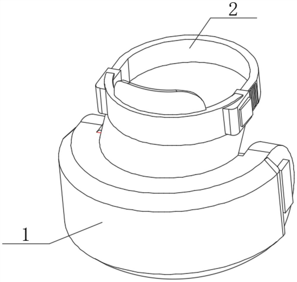
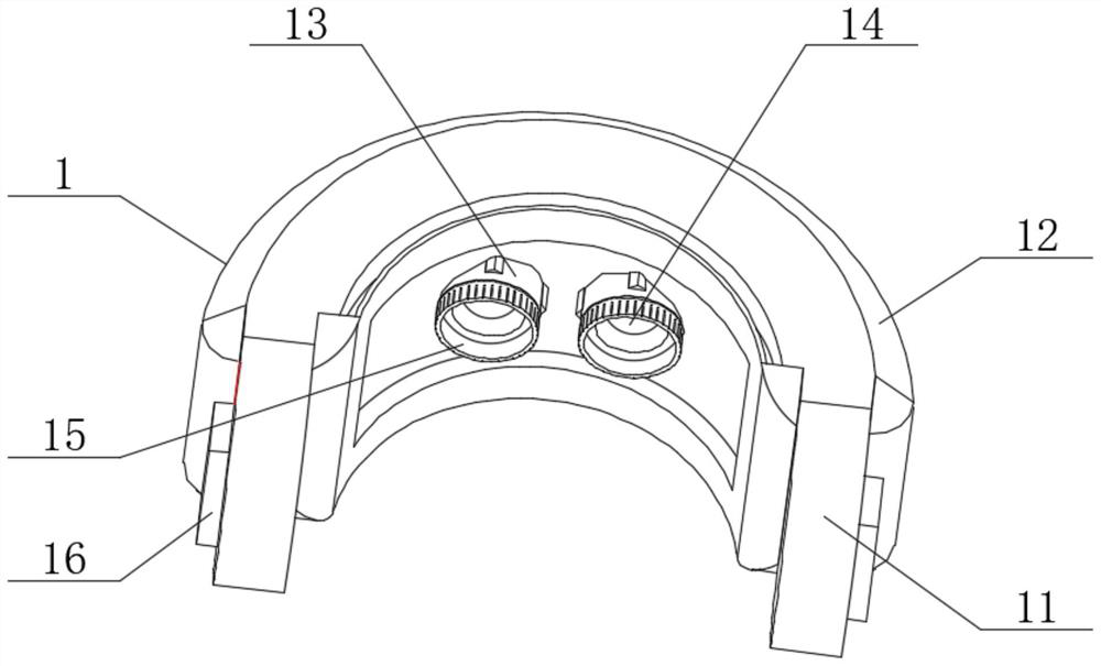
[0042] like figure 1 , figure 2 , image 3 and Figure 4 As shown, the present invention provides a technical solution: a retractable VR head-mounted device, including a retractable VR device 1 and a retractable head-mounted device 2, and the retractable head-mounted device 2 is installed on the top of the retractable VR device 1 , the telescopic VR device 1 includes a main frame 11, a display device 12, a telescopic frame 13, an inner display screen 14, a contact outer ring 15 and a control switch 16, the display device 12 is installed inside the main frame 11, and the telescopic frame 13 is installed in the main body Inside the frame 11, the terminals of the inner display screen 14 are connected to the terminals of the display device 12, the inner display screen 14 is installed inside the telescopic frame 13, the contact outer ring 15 is installed on the top of the telescopic frame 13, and the control switch 16 is installed On both sides of the main frame 11 , the termin...

Embodiment 2

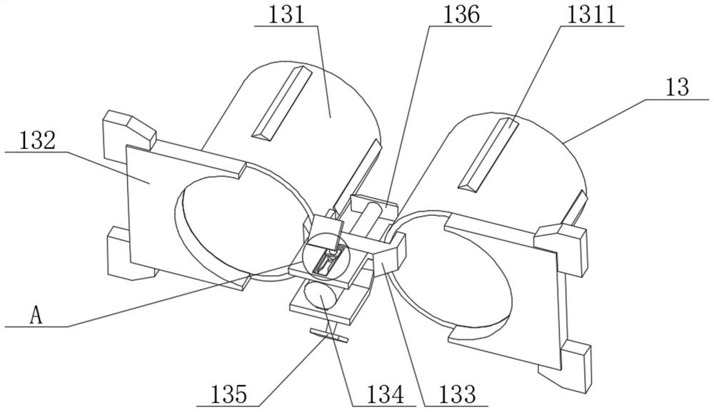
[0045] like figure 2 , image 3 and Figure 5 As shown, the drive structure 134 includes a drive motor 1341, a transmission support rod 1342, a bidirectional rod 1343, a movable turntable 1344, a transmission connection belt 1345, a return disc 1346 and a buckle 1347. The transmission support rod 1342 is arranged in a T-shape, and the transmission support rod One end of the 1342 is connected to the inside of the drive motor 1341, the two-way rod 1343 is installed on both ends of the transmission support rod 1342, the movable turntable 1344 is installed on the upper and lower ends of the two-way rod 1343, and one end of the transmission connecting belt 1345 is connected to the inside of the movable turntable 1344 , the other end of the transmission connecting belt 1345 is connected to the inside of the return disc 1346, one end of the buckle 1347 is connected to the inside of the return disc 1346, one end of the transmission support rod 1342 is connected to the inside of the ...

Embodiment 3

[0048] like figure 1 , Image 6 and Figure 7 As shown, the retractable head mounted device 2 includes a head strap 21, a fixed port 22, a forehead panel 23, a vertical panel 24 and a sliding structure 25. Both ends of the head strap 21 are connected to the interior of the fixed port 22, and are fixed The port 22 is mounted on the top of the forehead panel 23, the vertical panel 24 is mounted on the bottom of the forehead panel 23, the bottom of the vertical panel 24 is connected to the inside of the main body frame 11, and the sliding frame 25 is mounted between the vertical panel 24 and the main body frame 11. During the time, the sliding structure 25 includes a limit end 251, a positioning frame 252, a movable end 253 and a blocking plate 254. One end of the limit end 251 is connected to the inside of the main frame 11, and the bottom of the movable end 253 is connected to the vertical On the outer wall of the straight plate 24, one end of the positioning outer frame 252 ...


PUM


Abstract

The invention provides a telescopic VR head-mounted device and a use method thereof, and relates to the technical field of VR device.The telescopic VR head-mounted device comprises a telescopic VR device and a telescopic head-mounted device.The telescopic head-mounted device is installed at the top of the telescopic VR device, and the telescopic VR device comprises a main body frame, a display device, a telescopic framework, a display inner screen, a contact outer ring and a control switch; the display device is installed in the main body frame. According to the VR head-mounted equipment, the adjustable telescopic framework is arranged in the VR head-mounted equipment, and the specific length of the VR head-mounted equipment is automatically controlled, so that the visual field of a user can be completely covered when the VR head-mounted equipment is worn, and the visual field range of the user is concentrated on the display inner screen; by matching with an eyeshade equipped on the VR head-mounted equipment, the number of light rays entering the display equipment in the external environment can be greatly reduced, so that the influence of the light rays in the external environment on watching is reduced, and the use feeling of a wearer can be greatly improved.

Description

technical field [0001] The present invention relates to the technical field of VR devices, and in particular, to a retractable VR head-mounted device and a method for using the same. Background technique [0002] Virtual reality technology (ie VR technology), which specifically refers to a new human-computer interaction method created by means of computing or mobile terminals and the latest sensor technology. The existing virtual reality technology has not only been focused on the field of computer graphics. , it has become an important means of new product design and development. It is because virtual reality technology is a unique and novel technology, so it has attracted much attention and can give users a sense of immersion. People's vision and hearing are closed to the outside world, which guides users to have a feeling of being in a virtual environment. The display principle is that the left and right eye screens display images of the left and right eyes respectively....

Claims


Application Information

Patent Timeline
Patent Type & Authority Applications(China)
IPC IPC(8): G02B27/01
CPCG02B27/0176G02B2027/0178G02B2027/0192
Inventor 李大超
Owner 贵州云墨科技有限公司
Why Eureka
Try Eureka