
Device for displaying object position on near-eye second display screen and combination thereof

A technology for display screens and objects, applied in the input/output process of data processing, the input/output of user/computer interaction, instruments, etc. Controlling the human-computer interaction of the smartphone screen, etc., to achieve the effect of low manufacturing cost, easy customization, installation and adjustment, and accurate real-time human-computer interaction

Active Publication Date: 2022-07-22
艾视雅健康科技(苏州)有限公司
View PDF6 Cites 0 Cited by
  • Summary
  • Abstract
  • Description
  • Claims
  • Application Information

AI Technical Summary

Problems solved by technology

[0003] However, the touch screen and display screen in wearable devices, especially head-mounted smart devices, are often separate structures, such as VR or AR glasses connected to smartphones, because users can only see near-eye when wearing VR or AR glasses. The VR or AR display (second display) cannot see the smartphone screen (first display), so users cannot control the smartphone screen to achieve human-computer interaction when using VR or AR glasses
In the existing technology, there are several interactive methods such as detecting voice, eye tracking, or detecting gestures, but voice input and eye tracking have the disadvantages of being inaccurate and time-consuming, and the interactive mode of detecting gestures is easy to cause fatigue due to the need for hands to be suspended in the air and easy to misuse

Method used


Image

  • Device for displaying object position on near-eye second display screen and combination thereof
  • Device for displaying object position on near-eye second display screen and combination thereof
  • Device for displaying object position on near-eye second display screen and combination thereof

Examples


Embodiment Construction

[0032] The technical solutions in the embodiments of the present invention will be clearly and completely described below with reference to the accompanying drawings in the embodiments of the present invention. Obviously, the described embodiments are only a part of the embodiments of the present invention, rather than all the embodiments. Based on the embodiments of the present invention, all other embodiments obtained by those of ordinary skill in the art without creative efforts shall fall within the protection scope of the present invention. It should be noted that when a component is referred to as being "fixed to" or "disposed on" another component, it can be directly or indirectly on the other component. When an element is referred to as being "connected to" another element, it can be directly or indirectly connected to the other element. The orientation or positional relationship indicated by the terms "upper", "lower", "left", "right", etc. is based on the orientation...


PUM


Abstract

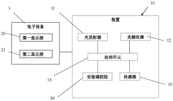
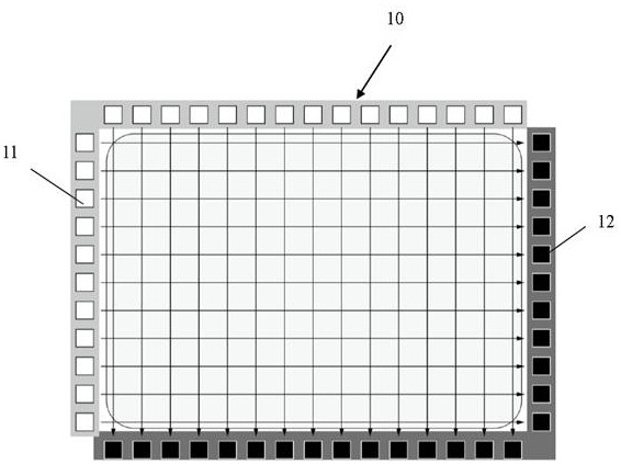
The invention discloses a device for displaying the position of an object on a near-eye second display screen and a combination thereof, which comprises at least one light emitter, at least one light receiver and a processing unit, the processing unit is configured to obtain a preset relative coordinate position of a light beam propagation path between the at least one light emitter and the at least one light receiver on the first display screen; when the object contacts or approaches the first display screen, the object interferes with the original light beam propagation path to change the light beam received by the light receiver to trigger at least one object positioning event; and the processing unit analyzes and obtains the relative coordinate position of the object and the first display screen based on the object positioning event and displays the relative coordinate position on the near-eye second display screen. Compared with the prior art, accurate and real-time man-machine interaction can be realized under the use scene that the touch screen and the display screen are separated and the touch screen is invisible, the manufacturing cost is low, and customization, installation and adjustment are easy.

Description

technical field [0001] The present invention relates to a device for displaying the position of an object on a second display screen near the eye and its combination. Background technique [0002] In the prior art, an intelligent electronic device such as a smart phone or a tablet computer usually uses a touch screen with a first display screen as an input device to realize human-computer interaction. For example, in a smartphone, since the touch screen and the display screen are integrated, when the user operates on the touch screen with a finger or a stylus and other objects, the icons displayed on the display screen can be seen, so the user's operation is intuitive and accurate. [0003] However, the touch screen and display screen in wearable devices, especially head-mounted smart devices, are often separate structures, such as VR or AR glasses connected to smartphones, because users can only see near eyes when wearing VR or AR glasses The VR or AR display screen (the s...

Claims


Application Information

Patent Timeline
Patent Type & Authority Applications(China)
IPC IPC(8): G06F3/041G06F3/042G06F3/0488G06F3/01
CPCG06F3/04162G06F3/0421G06F3/0488G06F3/011
Inventor 于林
Owner 艾视雅健康科技(苏州)有限公司
Learn More