
Carrier frequency offset estimation method based on zero subcarrier phase fitting

A technology of carrier phase and carrier frequency offset, which is applied in the direction of modulated carrier system, transmission monitoring, digital transmission system, etc., and can solve the problems affecting the estimation accuracy of carrier frequency offset

Active Publication Date: 2022-07-22
XIDIAN UNIV
View PDF6 Cites 0 Cited by
  • Summary
  • Abstract
  • Description
  • Claims
  • Application Information

AI Technical Summary

Problems solved by technology

[0008] Aiming at the above-mentioned deficiencies in the prior art, the present invention provides a method for estimating carrier frequency offset based on subcarrier phase fitting of zero number to solve multiple CFO candidate values Problems Affecting the Accuracy of Carrier Frequency Offset Estimation

Method used


Image

  • Carrier frequency offset estimation method based on zero subcarrier phase fitting
  • Carrier frequency offset estimation method based on zero subcarrier phase fitting
  • Carrier frequency offset estimation method based on zero subcarrier phase fitting

Examples


Embodiment 1

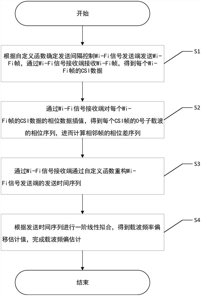
[0039] like figure 1 As shown, in an embodiment of the present invention, a carrier frequency offset estimation method based on the phase fitting of the zero sub-carrier includes the following steps:

[0040] S1. Determine the sending interval according to the user-defined function, control the Wi-Fi signal sending end to send Wi-Fi frames, receive the Wi-Fi frames through the Wi-Fi signal receiving end, and obtain the CSI data of each Wi-Fi frame;

[0041]S2. Interpolate the phase data of the CSI data of each Wi-Fi frame by the Wi-Fi signal receiving end to obtain the phase sequence of the zero-numbered subcarrier of each CSI frame, and then calculate the phase difference sequence of adjacent frames;

[0042] S3. Reconstruct the sending time series of the Wi-Fi signal sending end through a custom function through the Wi-Fi signal receiving end;

[0043] S4. Perform first-order linear fitting according to the transmission time sequence to obtain an estimated value of the carr...

Embodiment 2

[0067] This embodiment is directed to a specific implementation process of the method of the present invention.

[0068] The Wi-Fi signal sender sets the time interval for sending Wi-Fi frames through the self-defined function Z(i), and takes Z(i)| t=3μs,b=200μs =b+i×t, where parameter t and parameter b are customized. The Wi-Fi signal sender sends N_{pkt} Wi-Fi frames, for example, N_{pkt}=100, and the sent Wi-Fi frame should contain necessary information, such as Wi-Fi frame serial number and sending time. The Wi-Fi signal receiving end receives the Wi-Fi frame and parses it into the CSI data of the Wi-Fi frame, such as the CSI measurement frame number and transmission interval. The carrier column is interpolated to obtain the zero-numbered sub-carrier of each CSI frame, and the interpolated sub-carrier index sequence is K +0 . When using the Atheros 9300 network card as the Wi-Fi signal receiver, under the conditions of IEEE 802.11n protocol, 2.4GHz operating frequency, ...


PUM


Abstract

The invention discloses a carrier frequency offset estimation method based on zero subcarrier phase fitting, which comprises the following steps of: S1, determining a sending interval according to a custom function to control a Wi-Fi signal sending end to send Wi-Fi frames, and obtaining CSI (Channel State Information) data of each Wi-Fi frame; s2, phase data interpolation is carried out on the CSI data of each Wi-Fi frame through a Wi-Fi signal receiving end, and a phase difference sequence of adjacent frames is calculated; s3, reconstructing a sending time sequence of the Wi-Fi signal sending end through the Wi-Fi signal receiving end and a self-defined function; and S4, performing first-order linear fitting according to the sending time sequence to complete carrier frequency offset estimation. According to the invention, the influence of other error factors in the CSI is avoided through the use of the zero sub-carrier, the problem of multiple candidate values of the CFO is avoided through the non-equal interval sending strategy, and finally the accurate estimation of the CFO based on the CSI is realized.

Description

technical field [0001] The invention belongs to the technical field of channel measurement of wireless communication, and in particular relates to a carrier frequency offset estimation method based on the phase fitting of the zero subcarrier. Background technique [0002] Wi-Fi sensing technology relies on the sensitivity of CSI (Channel State Information) to environmental changes. The CFO (Carrier Frequency Offset) generated by the mismatch between the local crystal oscillators of Tx and Rx will bring cumulative phase errors to CSI. Therefore, CFO will directly hinder the performance improvement of Wi-Fi sensing and phase synchronization and phased array sensing. , distributed synchronization and other next-generation Wi-Fi communication and sensing technologies. [0003] The existing CFO estimation methods are all based on the Wi-Fi baseband signal and the specific segment structure in the baseband signal. to represent. And non-data-aided CFO estimation algorithms based...

Claims


Application Information

Patent Timeline
IPC IPC(8): H04B17/309H04L27/00H04W24/08
CPCH04B17/309H04L27/0014H04W24/08H04L2027/0026Y02D30/70
Inventor 蒋志平李瑞段渝于岂健王凯瑜段永辉蒋秋林
Owner XIDIAN UNIV
Learn More