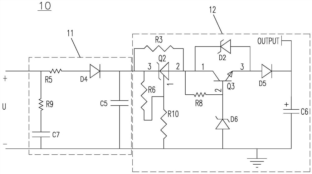
Abnormality test control circuit used in high-power power supply solution circuit
A technology for high-power power supply and abnormal testing, which is applied in the direction of emergency protection circuit devices, circuit devices, emergency protection circuit devices, etc. for limiting overcurrent/overvoltage, and can solve the problems of large drive space, complex circuit structure, and output current. Problems such as sudden changes cannot occur, and the effects of simplifying assembly and wiring, avoiding sudden changes, and reducing power supply specifications
- Summary
- Abstract
- Description
- Claims
- Application Information
AI Technical Summary
Problems solved by technology
Method used
Image

Examples
Embodiment Construction
[0023] In the following detailed description, reference is made to the accompanying drawings, which form a part hereof and are shown by way of illustrative specific embodiments in which the application may be practiced. In this regard, directional terms such as "top," "bottom," "left," "right," "top," "bottom," etc. are used with reference to the orientation of the figures being described. Because components of an embodiment may be positioned in several different orientations, directional terminology is used for purposes of illustration and is in no way limiting. It is to be understood that other embodiments may be utilized or logical changes may be made without departing from the scope of the present application. Therefore, the following detailed description should not be taken in a limiting sense, and the scope of the application is defined by the appended claims.
[0024] According to a first aspect of the present application, an abnormal test control circuit for use in a ...
PUM
 Abstract
Description
Claims
Application Information