Robotic arm path planning method, device, electronic equipment and storage medium

A path planning, robotic arm technology, applied in manipulators, program-controlled manipulators, manufacturing tools, etc., can solve problems such as large changes in joint space, large amount of calculation, and unstable operation of the manipulator, so as to ensure stability and avoid sudden changes. , the effect of avoiding singular solutions and multi-solution problems

Active Publication Date: 2021-11-26
JIHUA LAB
View PDF7 Cites 0 Cited by
  • Summary
  • Abstract
  • Description
  • Claims
  • Application Information

AI Technical Summary

Problems solved by technology

The existing manual path planning methods usually only meet the requirements of a simple working environment, and the degree of automation is low
In the existing method of automatic path planning based on spatial coordinates, when planning a path, every time a candidate path point is planned, inverse kinematics calculation is required to verify whether there is a collision or whether it is at a singular point (unclear The inverse of the robot is transformed into the coordinate point of the rotation angle of each joint axis of the robot, that is, the point where the inverse kinematics has no solution in the robot workspace), whether there is a multi-solution state, etc., the amount of calculation is large, and the path obtained by planning is sometimes just From the perspective of coordinates, it is smooth, but the rotation angle of the joint axis of the manipulator at adjacent path points changes greatly (that is, the joint space changes greatly), resulting in unstable operation of the manipulator and potential safety hazards

Method used


Image

  • Robotic arm path planning method, device, electronic equipment and storage medium
  • Robotic arm path planning method, device, electronic equipment and storage medium
  • Robotic arm path planning method, device, electronic equipment and storage medium

Examples


Embodiment Construction

[0036] Embodiments of the present invention are described in detail below, examples of which are shown in the drawings, wherein the same or similar reference numerals denote the same or similar elements or elements having the same or similar functions throughout. The embodiments described below by referring to the figures are exemplary only for explaining the present invention and should not be construed as limiting the present invention.

[0037] In describing the present invention, it should be understood that the terms "center", "longitudinal", "transverse", "length", "width", "thickness", "upper", "lower", "front", " Orientation indicated by rear, left, right, vertical, horizontal, top, bottom, inside, outside, clockwise, counterclockwise, etc. The positional relationship is based on the orientation or positional relationship shown in the drawings, which is only for the convenience of describing the present invention and simplifying the description, rather than indicating ...


PUM


Abstract

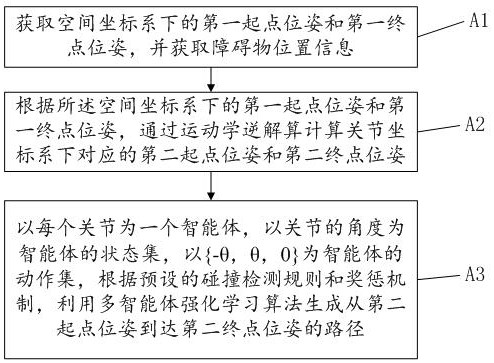
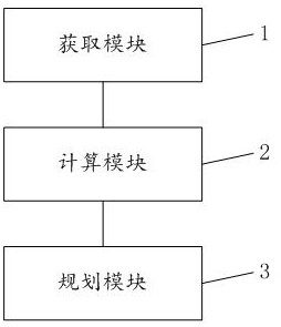
The present invention relates to the technical field of robotic arm control, and provides a robotic arm path planning method, device, electronic equipment, and storage medium, by obtaining the first starting point pose and the first end point pose in a space coordinate system, and obtaining obstacles Position information; according to the first starting point pose and the first end point pose in the space coordinate system, the corresponding second start point pose and the second end point pose in the joint coordinate system are calculated through kinematics inverse calculation; each joint As an agent, the angle of the joint is the state set of the agent, and {‑θ, θ, 0} is the action set of the agent. According to the preset collision detection rules and reward and punishment mechanism, the multi-agent reinforcement learning algorithm is used Generate a path from the second starting point pose to the second end point pose; where, θ is the preset minimum motion step size of each joint; thus avoiding the problem caused by calculating the angle of each joint through the inverse kinematics calculation of the space coordinates Singular solutions and multi-solution problems, and ensure the smooth operation of the robotic arm.

Description

technical field [0001] The present invention relates to the technical field of manipulator control, in particular to a manipulator path planning method, device, electronic equipment and storage medium. Background technique [0002] The path planning technology of the manipulator is an important link in the control technology of the manipulator. The main purpose of the path planning of the manipulator is to enable the manipulator to reach the designated end point from the designated starting point without collision. The existing manual path planning methods usually only meet the requirements of a simple working environment, and the degree of automation is low. In the existing method of automatic path planning based on spatial coordinates, when planning a path, every time a candidate path point is planned, inverse kinematics calculation is required to verify whether there is a collision or whether it is at a singular point (unclear The inverse of the robot is transformed into...

Claims


Application Information

Patent Timeline
Patent Type & Authority Patents(China)
IPC IPC(8): B25J9/16
CPCB25J9/1664B25J9/1602
Inventor 张校志钟泽邦吴宇君陈良煜
Owner JIHUA LAB
Why Eureka
Try Eureka