Method for separating elastomeric particles

A technology of elastomers and granules, applied in applications, household appliances, and other household appliances, etc., can solve problems such as long disassembly and unusable time, long execution time, and complexity

Pending Publication Date: 2022-07-22
MICHELIN & CO CIE GEN DES ESTAB MICHELIN
View PDF3 Cites 0 Cited by
  • Summary
  • Abstract
  • Description
  • Claims
  • Application Information

AI Technical Summary

Problems solved by technology

This also leads to dismantling and unavailability of molds for potentially long periods and incompatibility with industrial requirements
[0003] Unfortunately, this method is co

Method used


Image

  • Method for separating elastomeric particles
  • Method for separating elastomeric particles
  • Method for separating elastomeric particles

Examples


Embodiment Construction

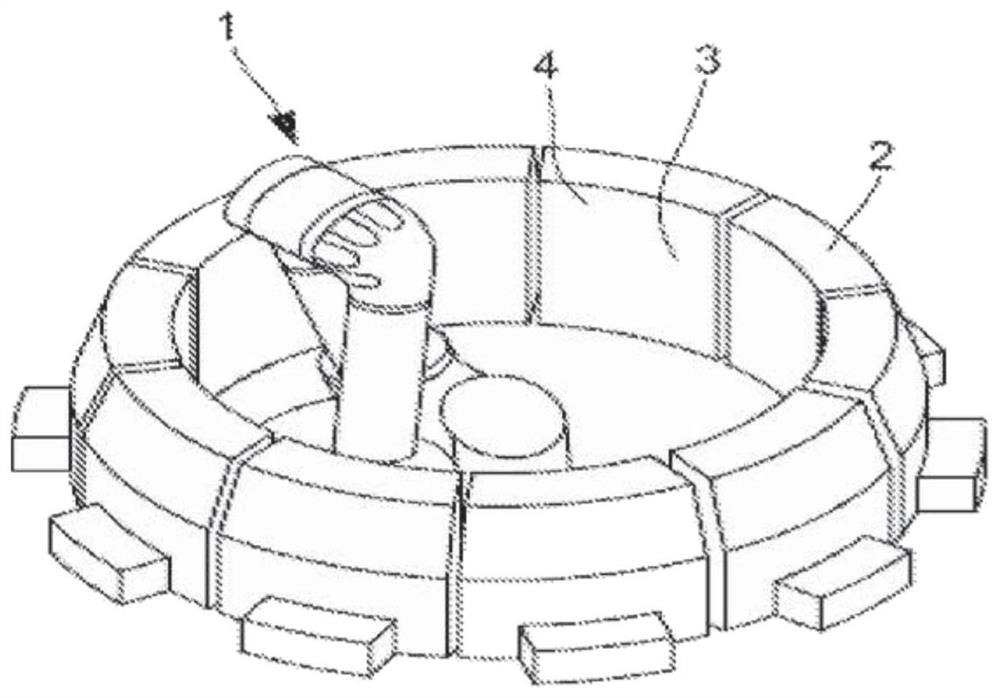
[0015] like figure 1 As shown, a cleaning device, designated generally by the reference numeral 1 , is provided in the tire curing mold 2 . The mould 2 includes a plurality of microvalves 3 arranged on the entire inner surface 4 thereof.

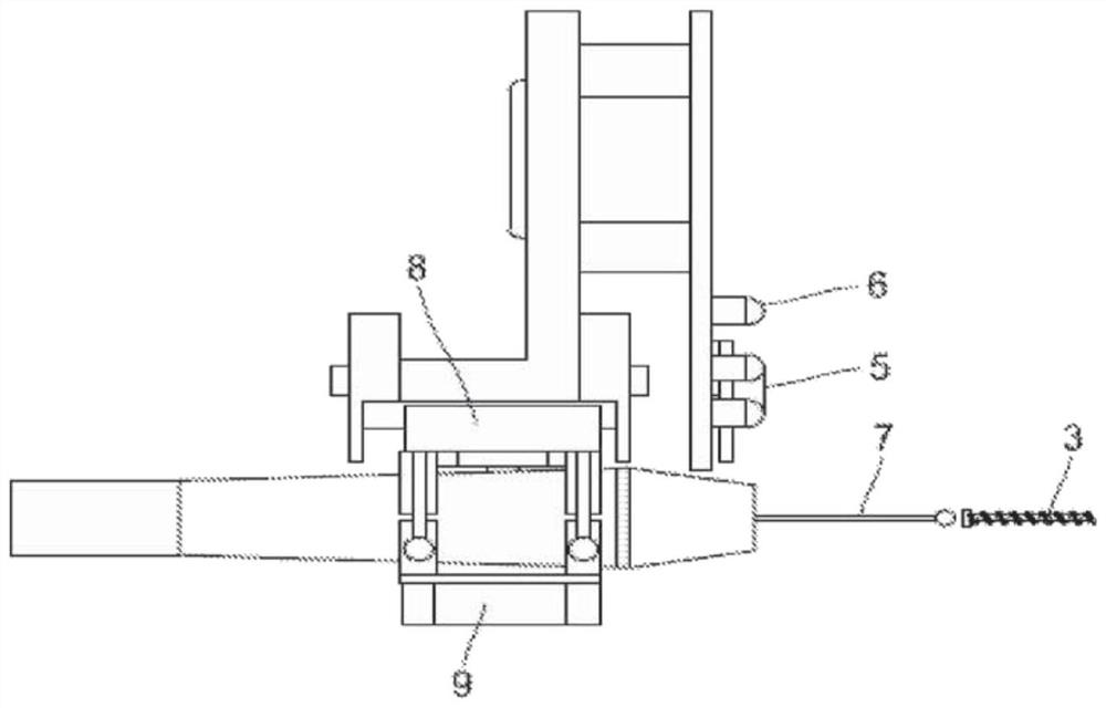
[0016] like figure 2 Shown in more detail, the device includes a camera 5 for detecting each microvalve 3 . The camera 5 is associated with an algorithm of the "Hough Circle Transform" type via a computer (not shown). The algorithm can perform a complete reading of the inner surface 4 of the mold 2 . The camera 5 is illuminated by a light source 6 of LED type. The device further comprises an ultrasonic pen 7 mounted on a track 8 for gradually bringing the pen into contact with the microvalve and an accelerometer 9 for detecting changes in frequency indicating the end of cleaning of the microvalve . Instead of an accelerometer, a microphone could be used, which would be used to record changes in vibration frequency by clicking.

[001...


PUM


Abstract

The invention relates to a method for separating elastomeric particles attached to microvalves (3) arranged on the inner surface of a vehicle tyre vulcanisation mould (2). The method is characterized by: detecting the presence of a microvalve (3) provided on said inner surface of the mould; during separation of particles from the microvalve (3), the microvalve (3) is vibrated at a constant amplitude of between about 0.05 mm and 0.2 mm and a frequency of between 20000 Hz and 30000 Hz.

Description

technical field [0001] The present invention relates to a method for separating elastomer particles adhering to the surface of a microvalve provided on the inner surface of a tire vulcanization mold. Background technique [0002] From application WO 2016 / 105306, a method for cleaning microvalves of tire vulcanization moulds is known, the method comprising subjecting all moulds in a dry state to ultrasonic waves before cleaning them, then rinsing and drying all moulds Immerse in cleaning solution. This also results in a potentially long period of disassembly and unavailability of the mold and incompatibility with industry requirements. [0003] Unfortunately, this method is complicated due to the number of steps and the long execution time. Furthermore, this method does not allow targeted cleaning of the valve, and therefore a possible careful cleaning of the valve. [0004] Therefore, there remains a need for a method that enables targeted inspection of the interior regio...

Claims


Application Information

Patent Timeline
IPC IPC(8): B29D30/06
CPCB29D30/0662B29D2030/0663B08B9/00B08B2209/005
Inventor J-M·德托雷F·德拉戈M·德吕埃C·皮克L·席尔瓦
Owner MICHELIN & CO CIE GEN DES ESTAB MICHELIN
Why Eureka
Try Eureka