Vacuum magnetic levitation pipeline structure

A vacuum and maglev technology, used in roads, tracks, tunnel systems, etc., can solve the problems of axial deformation of pipelines, damage to pipeline connections, and damage to vacuum maglev pipeline structure, etc., to ensure independence and avoid axial deformation.

Active Publication Date: 2022-07-26
CHINA RAILWAY SIYUAN SURVEY & DESIGN GRP
View PDF16 Cites 0 Cited by
  • Summary
  • Abstract
  • Description
  • Claims
  • Application Information

AI Technical Summary

Problems solved by technology

At present, the simple use of flange rigid connection between vacuum maglev pipelines will lead to axial deformation of the pipeline, damage the connection between the pipeline and the foundation, and eventually damage the structure of the vacuum maglev pipeline, resulting in the operation of the maglev train being affected

Method used


Image

  • Vacuum magnetic levitation pipeline structure
  • Vacuum magnetic levitation pipeline structure
  • Vacuum magnetic levitation pipeline structure

Examples


Embodiment Construction

[0025] In order to make the objectives, technical solutions and advantages of the present invention clearer, the present invention will be further described in detail below with reference to the accompanying drawings and embodiments. It should be understood that the specific embodiments described herein are only used to explain the present invention, but not to limit the present invention. In addition, the technical features involved in the various embodiments of the present invention described below can be combined with each other as long as they do not conflict with each other.

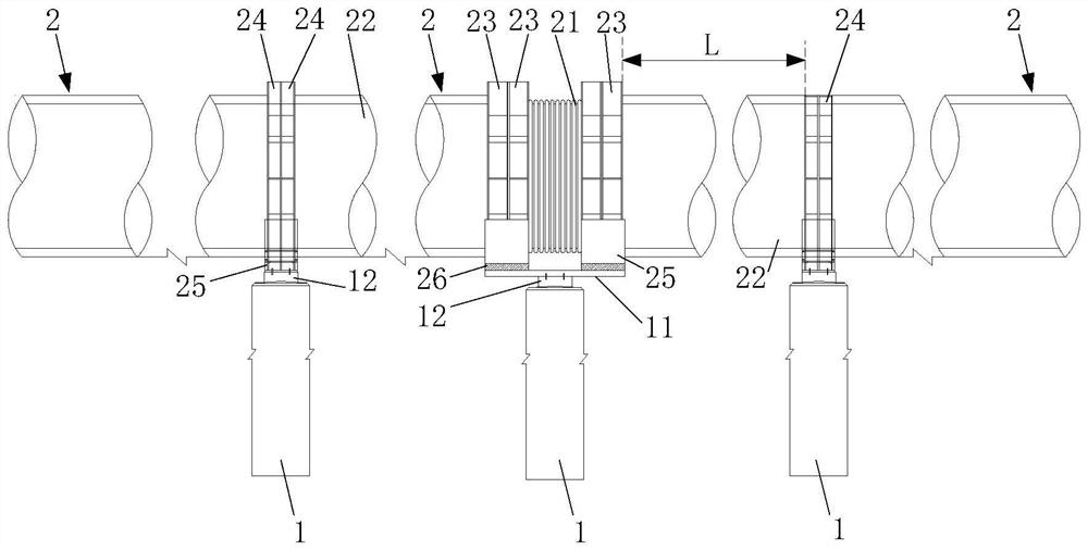
[0026] figure 1 It is a schematic structural diagram of a vacuum maglev pipeline structure provided by the embodiment of the present invention, such as figure 1 As shown, the vacuum maglev pipeline structure includes a plurality of bridge piers 1 and a plurality of vacuum maglev pipeline units 2 arranged in sequence.

[0027] A plurality of bridge piers 1 are arranged in parallel and spaced apart....


PUM


Abstract

The invention discloses a vacuum maglev pipeline structure, and belongs to the technical field of vacuum high-speed maglev traffic. The vacuum maglev pipeline structure comprises a plurality of piers and a plurality of vacuum maglev pipeline units. The multiple piers are arranged in parallel at intervals. Each vacuum magnetic levitation pipeline unit comprises a vacuum corrugated pipe and two vacuum magnetic levitation pipelines which are coaxially arranged, one end of the vacuum corrugated pipe is communicated with one end of one vacuum magnetic levitation pipeline through two sliding flanges, and the other end of the vacuum corrugated pipe is communicated with one end of the other vacuum magnetic levitation pipeline through two sliding flanges; and the other end of one vacuum magnetic suspension pipeline and the other end of the other vacuum magnetic suspension pipeline are respectively communicated with the adjacent vacuum magnetic suspension pipeline through two fixing flanges. The vacuum magnetic levitation pipeline structure provided by the embodiment of the invention not only can disperse temperature stress, but also can avoid transmission and accumulation of the temperature stress, so that the vacuum magnetic levitation pipeline structure can be prevented from being damaged.

Description

technical field [0001] The invention belongs to the technical field of vacuum high-speed maglev transportation, and more particularly relates to a vacuum maglev pipeline structure. Background technique [0002] Vacuum high-speed maglev transportation technology is a technology that combines vacuum pipeline and maglev technology. Due to breaking through the constraints of air resistance, noise and wheel-rail adhesion, the speed can reach 600-1000km / h, filling the gap between high-speed rail and air transportation. Speed ​​blank area. With the breakthrough of high-power traction drive technology, it can reach 1000km / h and above, or even higher speeds of supersonic or supersonic speed, becoming a long-distance urban or ultra-long-distance intercontinental transportation mode that supplements or replaces aviation in the future. [0003] However, for a vacuum maglev pipeline of several hundred kilometers, temperature stress will be generated under the influence of aerodynamic he...

Claims


Application Information

Patent Timeline
Patent Type & Authority Applications(China)
IPC IPC(8): B61B13/10B61B13/08B60L13/04
CPCB61B13/10B61B13/08B60L13/04Y02T30/00
Inventor 张琨王剑涛张银龙张浩光振雄董云松殷勤邱绍峰周明翔李加祺刘辉张俊岭彭方进李成洋何杰
Owner CHINA RAILWAY SIYUAN SURVEY & DESIGN GRP
Why Eureka
Try Eureka