Visual drainage tube

A technology of drainage tube and drainage bottle, which is applied in the field of medical equipment

Inactive Publication Date: 2022-07-29
THE FIRST AFFILIATED HOSPITAL OF XINXIANG MEDICAL UNIV
View PDF0 Cites 0 Cited by
  • Summary
  • Abstract
  • Description
  • Claims
  • Application Information

AI Technical Summary

Problems solved by technology

[0004] In view of the above situation, in order to overcome the defects of the prior art, the present invention provides a visual drainage tube. The present invention has a novel structure, ingenious concept, simple and convenient operation, effectively solves the problem of cleaning the drainage fluid in time, and adds the function of preventing blockage. Added the function of observing the internal drainage status, added the function of cleaning the tube to prevent backflow, and added the function of fixing it on the patient

Method used


Image

  • Visual drainage tube
  • Visual drainage tube
  • Visual drainage tube

Examples


Embodiment 1

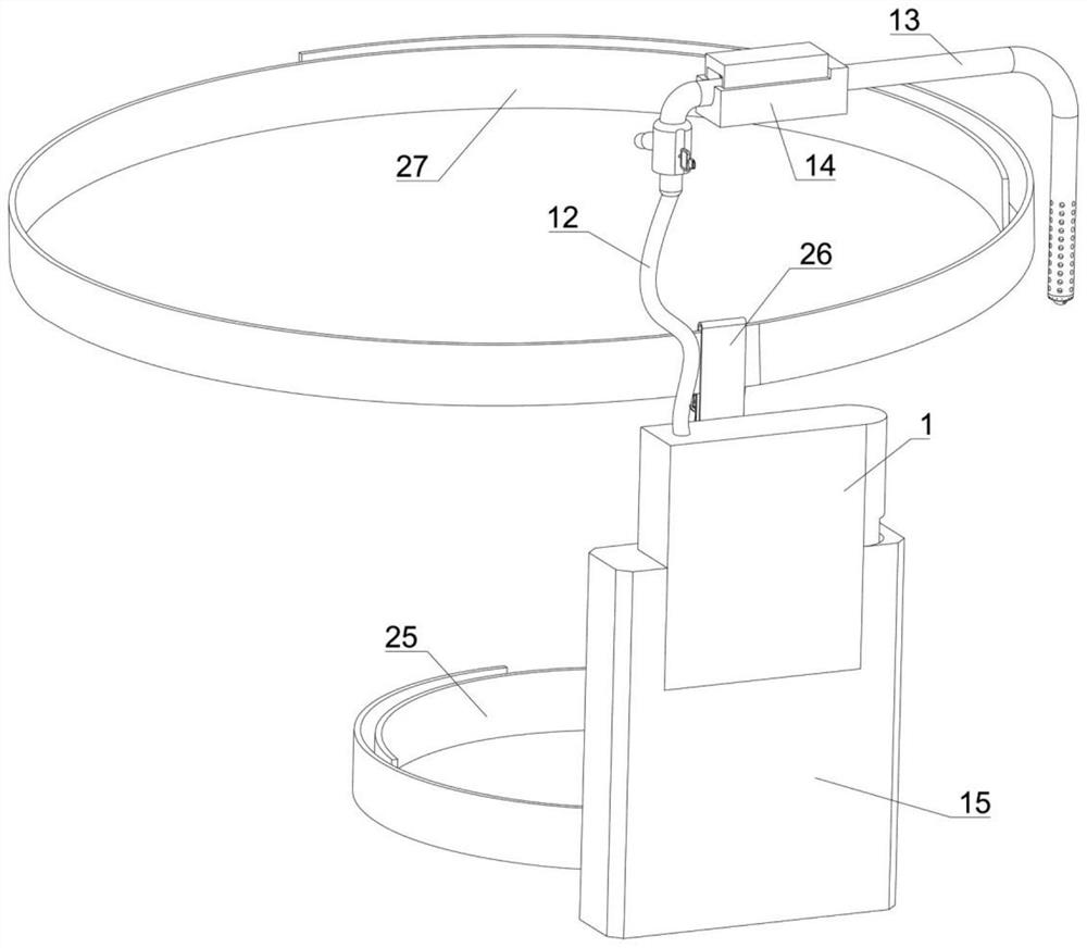
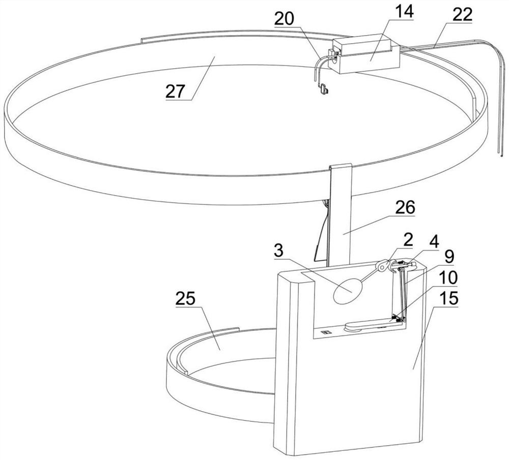
[0035] Example one, by Figure 1-Figure 6Given, in order to achieve the purpose of preventing liquid backflow, including a drainage bottle 1, a cam 2 is rotatably connected to the inside of the drainage bottle 1, a floating ball 3 is fixedly connected to the lower end of the cam 2, and the inside of the drainage bottle 1 A T rod 4 is slidably connected, the T rod 4 is T-shaped and one end of the T rod 4 is arc-shaped, the right end of the T rod 4 is fixedly connected with a first pressing rod 5, and the upper end of the T rod 4 is fixed A tension spring 6 is connected, the other end of the tension spring 6 is fixedly connected with the drainage bottle 1, and a toothed pulley 7 is rotatably connected to the inside of the drainage bottle 1. The toothed pulley 7 is composed of a gear and a pulley, so The toothed pulley 7 meshes with the T-bar 4, and the inside of the drainage bottle 1 is rotatably connected with a rotating wheel 8. The rotating wheel 8 is composed of a pulley and...

Embodiment 2

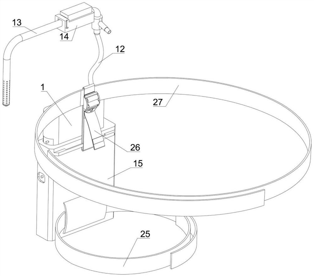
[0037] Embodiment 2, on the basis of Embodiment 1, by figure 1 , figure 2 , image 3 , Figure 7 , Figure 8 and Figure 9 Given, in order to achieve the purpose of preventing pipeline blockage, the pressing mechanism 14 includes a pressing box 1401 slidably connected with the second pipeline 13, and a pressing block 1402 is slidably connected inside the pressing box 1401. The pressing block The lower end of 1402 is fixedly connected with a plurality of moving springs 1403, the inside of the pressing block 1402 is fixedly connected with a plurality of pressing columns 1404, and the inside of the pressing box 1401 is slidably connected with a pressing block 1405. The pressing box 1401 A limit block 1406 is fixedly connected inside the limit block 1406, and a limit spring 1407 is fixedly connected to the left end of the limit block 1406;

[0038] When the liquid in the pipeline is thick and blocked, slide the pressing box 1401 to the designated position, and then slide the...

Embodiment 3

[0039] Embodiment 3, on the basis of Embodiment 1, by Figure 10 and Figure 11 Given, in order to achieve the purpose of fixing the drainage bottle, the fixing mechanism 16 includes a push plate 1601 slidably connected with the waste liquid bottle 15, and the upper end of the push plate 1601 is fixedly connected with two first barbs 1602, so A return spring 1603 is fixedly connected to the left end of the push plate 1601, a second pressing rod 1604 is fixedly connected to the right end of the push plate 1601, and two second barbs 1605 are fixedly connected to the lower end of the drainage bottle 1. A barb 1602, a push plate 1601, a second pressing rod 1604, a return spring 1603 and the first barb 1602 cooperate with each other to form the limiting structure of the drainage bottle 1;

[0040] When the drainage bottle 1 needs to be fixed on the waste bottle 15 , insert the second barb 1605 on the drainage bottle 1 into the waste bottle 15 , and the second barb 1605 will touch ...


PUM


Abstract

A visual drainage tube effectively solves the problem of timely cleaning drainage liquid and comprises a drainage bottle, a cam is rotatably connected to the interior of the drainage bottle, a floating ball is fixedly connected to the lower end of the cam, a T-shaped rod is slidably connected to the interior of the drainage bottle, a first pressing rod is fixedly connected to the right end of the T-shaped rod, and a second pressing rod is fixedly connected to the right end of the T-shaped rod. The upper end of the T-shaped rod is fixedly connected with a tension spring, the other end of the tension spring is fixedly connected with the drainage bottle, a toothed belt wheel is rotationally connected into the drainage bottle and meshed with the T-shaped rod, a rotating wheel is rotationally connected into the drainage bottle, and a transmission belt is arranged between the rotating wheel and the toothed belt wheel in a sleeved mode. The device is novel in structure, ingenious in conception and easy and convenient to operate, the function of preventing blockage is added, the function of observing the internal drainage state is added, the function of preventing backflow of the cleaning pipe is added, and the function of being fixed to the body of a patient is added.

Description

technical field [0001] The present invention relates to the technical field of medical devices, in particular to a visual drainage tube. Background technique [0002] The purpose of surgical drainage is to guide pus, blood, and liquid accumulated between human tissues or body cavities to the outside of the body to prevent postoperative infection and affect wound healing. Medical staff check back and forth to see if the flow is full, which increases the burden on medical staff. Failure to replace it in time after full flow will cause backflow, which will cause secondary damage to the patient. When the liquid in the drainage tube is thick and blocked, the doctor needs to squeeze repeatedly with both hands. Pressing the drainage tube increases the work intensity for medical staff. It is impossible to observe the drainage status in the body, the bleeding at the surgical site, and the purpose of judging the presence or absence of anastomotic fistula and the size of the fistula. ...

Claims


Application Information

Patent Timeline
IPC IPC(8): A61M1/00A61M25/00A61M25/02A61B1/04
CPCA61M25/0021A61M25/0043A61M25/0082A61M25/02A61B1/04A61M2025/0019A61M2025/0206A61M2025/0213A61M2025/0253
Inventor 陈炳合杜学芳李帅超谭用
Owner THE FIRST AFFILIATED HOSPITAL OF XINXIANG MEDICAL UNIV
Why Eureka
Try Eureka