Fuel cell hybrid power system

A technology of hybrid power system and fuel cell, which is applied in the direction of electric vehicles, battery circuit devices, battery/battery traction, etc., can solve the problems of output interruption, large spare power, high equipment cost, etc., achieve quick response and avoid power fluctuations , the effect of meeting the requirements of super power and low power operation

Pending Publication Date: 2022-07-29
安徽伯华氢能源科技有限公司 +1
View PDF0 Cites 0 Cited by
  • Summary
  • Abstract
  • Description
  • Claims
  • Application Information

AI Technical Summary

Problems solved by technology

However, when the load is used at a low power, even if the matched high-power fuel cell works at a low power, its spare power is still large, which will cause high equipment costs and waste energy.
Therefore, when the fuel cell is in use, it is often necessary to activate the catalyst of the fuel cell by short-circuiting the output end, and the short-circuit will cause the output to be interrupted and affect the efficiency of electricity use.
The existing power system generally introduces rechargeable batteries, and switches to rechargeable battery power supply when the fuel cell power supply is insufficient, or fuel cell and rechargeable battery power supply at the same time, but this method still has the problem of working power fluctuations, which needs to be based on power needs Regulating the output power of the fuel cell

Method used


Image

  • Fuel cell hybrid power system
  • Fuel cell hybrid power system
  • Fuel cell hybrid power system

Examples


Embodiment Construction

[0029] In order to make the objectives, technical solutions and advantages of the present invention clearer, the present invention will be further described in detail below with reference to the accompanying drawings and embodiments. It should be understood that the specific embodiments described herein are only used to explain the present invention, but not to limit the present invention.

[0030] It should be noted that when an element is referred to as being "mounted on," "fixed to," or "disposed on" another element, it can be directly on the other element or an intervening element may also be present. When an element is referred to as being "connected to" another element, it can be directly connected to the other element or intervening elements may also be present.

[0031] It should also be noted that the azimuth terms such as left, right, upper and lower in the embodiments of the present invention are only relative concepts to each other or refer to the normal use state ...


PUM


Abstract

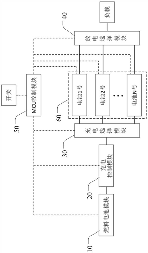
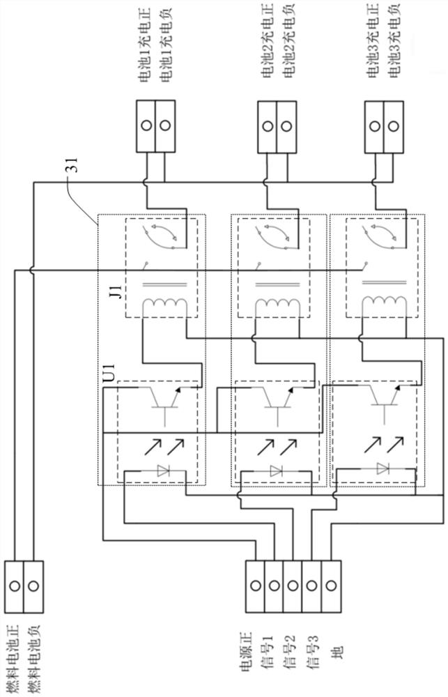
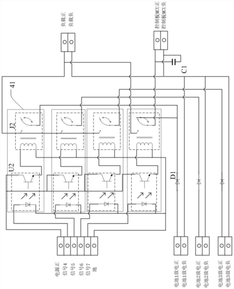
The invention discloses a fuel cell hybrid power system, which comprises a fuel cell module, a charging control module, a charging selection module, a discharging selection module, an MCU control module and a plurality of rechargeable batteries, and is characterized in that the MCU control module obtains the voltage of each rechargeable battery, and when the voltage of a certain rechargeable battery is lower than a set value, the MCU control module controls the charging selection module and the discharging selection module; when the rechargeable battery supplies power to the load, the rechargeable battery stops supplying power and is switched to other rechargeable batteries for supplying power at the same time, the fuel battery module and the charging control module are enabled, and the charging control module carries out boosting and current limiting processing on electric energy output by the fuel battery module and charges the rechargeable battery. The rechargeable battery can provide the required load power in time when the load is required to be high, the rechargeable battery does not need to wait when being started, and the fuel cell module only needs to keep stable operation power, so that the fluctuation of the power of the fuel cell is avoided, and the load can be quickly responded.

Description

technical field [0001] The invention relates to a hybrid power management technology, in particular to a fuel cell hybrid power system. Background technique [0002] When the existing power system is powered by a fuel cell alone, there is a defect that it takes a period of time to reach a stable power state during startup. When the instantaneous start-up power of the load is much greater than the rated power, if only the fuel cell is used for power supply, a high-power fuel cell needs to be selected, and the output power of the fuel cell needs to be increased. When the load is used at a lower power, even if the matched high-power fuel cell works at a lower power, its spare power is still relatively large, which will cause problems of high equipment cost and waste of energy. Therefore, the fuel cell also needs to frequently activate the catalyst of the fuel cell by short-circuiting the output terminal during use, and the short-circuiting will cause the output to be interrupt...

Claims


Application Information

Patent Timeline
Patent Type & Authority Applications(China)
IPC IPC(8): B60L50/70B60L50/75B60L50/60H02J7/00
CPCB60L50/70B60L50/75B60L50/60H02J7/0013H02J7/0025H02J7/0068H02J7/0063H02J2300/30
Inventor 刘文强王广华林旭岚马凯成冯柄楠
Owner 安徽伯华氢能源科技有限公司
Why Eureka
Try Eureka