Low-stroboflash AC LED circuit

A LED light string and LED drive technology, applied in electric light sources, electrical components, electroluminescent light sources, etc., can solve problems such as adverse stimulation of the visual nerve center, eye fatigue and even headaches, and achieve reduced switching power and stroboscopic flicker , Improve the effect of power factor

Active Publication Date: 2016-09-14
北京易美新创科技有限公司
View PDF6 Cites 0 Cited by
  • Summary
  • Abstract
  • Description
  • Claims
  • Application Information

AI Technical Summary

Problems solved by technology

The frequency of the full-wave rectified input voltage is usually around 100Hz. Such a stroboscopic frequency will cause adverse stimulation to the human visual nerve center, which may easily cause symptoms such as eye fatigue and even headaches.

Method used


Image

  • Low-stroboflash AC LED circuit
  • Low-stroboflash AC LED circuit
  • Low-stroboflash AC LED circuit

Examples


Embodiment 1

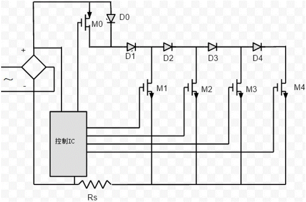
[0026] Embodiment 1: see figure 1 , a low-frequency flashing AC LED drive circuit, including: drive IC, LED light string D0, LED light string D1, LED light string D2, LED light string D3, LED light string D4, PMOS tube M0, PMOS tube M1, PMOS tube M2, PMOS tube M3, PMOS tube M4, current limiting resistor Rs;

[0027] The control IC is used to control the gate voltage of PMOS transistor M0, PMOS transistor M1, PMOS transistor M2, PMOS transistor M3, and PMOS transistor M4;

[0028] The positive pole of the LED light string D0 is connected to the source level of the PMOS tube M0, and the negative pole of the LED light string D0 is connected to the drain level of the PMOS tube M0;

[0029] LED light string D0, LED light string D1, LED light string D2, LED light string D3, LED light string D4 are connected in series, the conduction voltage of LED light string D0 is less than half of the conduction voltage of LED light string D4 ;The maximum power of LED light string D1, LED ligh...

Embodiment 2

[0041] Embodiment 2. On the basis of the low-flicker AC LED drive circuit in Embodiment 1, a valley-filling circuit is added to the DC power supply end. The valley-filling circuit is used to improve the power factor of the DC power supply, thereby reducing stroboscopic flicker.

Embodiment 3

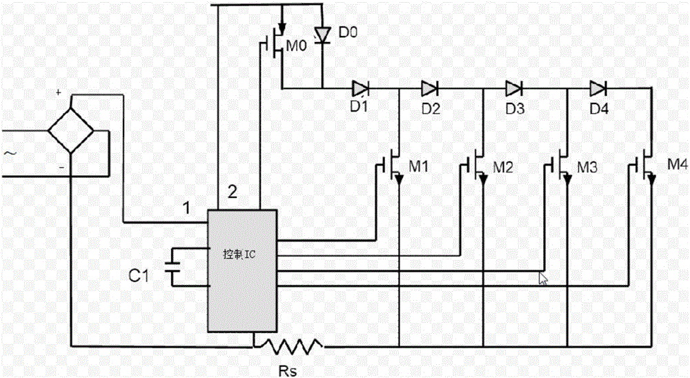
[0042] Example 3, see figure 2 , on the basis of a low-frequency flashing AC LED drive circuit in Embodiment 1, the energy storage capacitor control pin of the drive IC is added with an energy storage capacitor C1. When the drive IC judges that the input DC power is zero, the LED light string D0, Light string D1, LED light string D2, LED light string D3, LED light string D4 power supply, eliminate the DC power supply when the LED light string D0, LED light string D1, LED light string D2, LED light string D3, LED light string D4 Strobe caused by extinguishing.


PUM


Abstract

The invention discloses a low-stroboflash AC LED (Light Emitting Diode) driving circuit. The low-stroboflash AC LED driving circuit comprises a driver IC, an LED lamp string D0, an LED lamp string D1, an LED lamp string D2, an LED lamp string D3, an LED lamp string D4, a PMOS tube M0, a PMOS tube M1, a PMOS tube M2, a MPOS tube M3, a PMOS tube M4 and a current-limiting resistor Rs. According to the flow-stroboflash AC LED driving circuit, a method of combining grid electrode negative feedback with source electrode feedback is adopted to control breakover current of different LED sections, so that consistent total load power of the LEDs at different voltages is kept and the luminous flux change of each LED is very small; a structure with a small current at a low voltage and a large current at a high voltage is adopted, so that the LED load power in a wide-range input voltage section is kept steady; as a high-end PMOS control tube and an LED series circuit are adopted, a system at the low voltage still has a relatively high efficiency; and the driving efficiency is increased radically, the power factor is increased, the MOS tube switching power is reduced and the stroboflash is decreased.

Description

technical field [0001] The invention belongs to the technical field of semiconductor lighting applications, in particular to a low-frequency flicker AC LED circuit structure. Background technique [0002] At present, LED chips have been widely used in the field of new energy-saving light sources due to their high efficiency, high integration and long life. In LED light sources, power drive is a key technology. Due to the high integration and low cost requirements of LED applications, AC LED drive solutions without inductance and capacitors and other energy storage devices are taking an increasing share in the market. In this type of driving scheme, the control IC controls the number of LEDs that the actual conduction current passes through by adjusting the gate voltage of the LED pass switch MOS tube, so as to compensate for the excessive conduction current to the input voltage caused by the non-linearity of the LED. Sensitive, so as to achieve the purpose of current limit...

Claims


Application Information

Patent Timeline
IPC IPC(8): H05B33/08H05B44/00
CPCH05B45/37
Inventor 冯向光孙国喜范振灿
Owner 北京易美新创科技有限公司
Why Eureka
Try Eureka