Novel concrete apron structure and construction method thereof
A construction method and concrete technology, which is applied in the direction of infrastructure engineering, construction, protection devices, etc., can solve the problems of concrete water cracking and other problems, and achieve the effect of ensuring the overall performance
- Summary
- Abstract
- Description
- Claims
- Application Information
AI Technical Summary
Problems solved by technology
Method used
Image
Examples
Embodiment 1
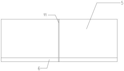
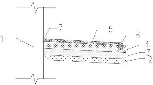
[0033] Example 1: by Figure 1 to Figure 3 Given, a new type of concrete water-scattering structure, the water-scattering structure as a whole forms an inclined downward slope from the outer wall 1, and the water-scattering structure sequentially includes a backfill lime soil base 3, an anti-frost-heave layer 4 and concrete from bottom to top. For the water-spraying surface layer, separating devices 11 are arranged at intervals in the concrete water-dispersing surface layer. The separating device 11 separates the whole concrete water-dispersing surface layer into a plurality of small parts, and the concrete shrinkage amount is within a reasonable range and will not cause cracking.
Embodiment 2
[0034] Embodiment 2: On the basis of Embodiment 1, the concrete water-scattering surface layer includes a concrete water-scattering slope-seeking layer 5 and a concrete water-scattering interlocking layer 6, and the concrete water-scattering interlocking layer is embedded in the anti-frost heave layer 4 and forms a slope with the concrete water-scattering interlocking layer. Layer 5 is connected to form an inverted L-shaped concrete sprinkling surface layer. In the existing sprinkling structure, the concrete sprinkling surface layer and the anti-frost heave layer are directly laid, and the connection between the two layers is not tight enough, and the soil layer is easily damaged when washed by rainwater , subsidence and cracking occur, and the structure that the water-dispersing surface layer is directly embedded in the lower layer can avoid the above situation.
Embodiment 3
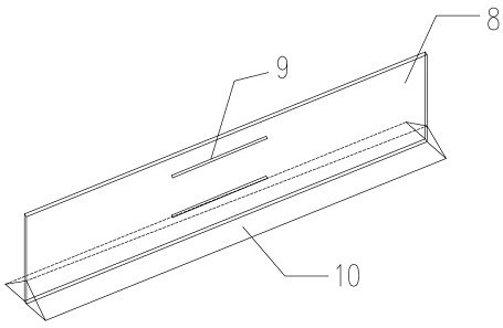
[0035] Embodiment 3: On the basis of the above-mentioned embodiment, the separating device 7 includes two baffles 8 connected by rubber strips 9, and the strength of the two baffles is relative to one baffle, in the concrete pouring, can be more guaranteed. For strength, the bottom of each baffle 8 is provided with a corner protection structure 10, and the corner protection is used to fix the double glass strips to ensure that the separation device 7 is vertical.
[0036] In the above embodiment, the baffle 8 can be made of plexiglass. The plexiglass has high strength, is not easy to break, and will not deform or rot even if it is placed in concrete for a long time.
[0037] On the basis of the above-mentioned embodiments, the width of the concrete water-spraying occlusal layer is between 180mm and 200mm, and the depth is between 330mm and 350mm, and separating devices 11 are arranged at intervals of 4m-5m between the concrete water-distributing surface layers. Even if the con...
PUM
 Abstract
Description
Claims
Application Information
 - R&D Engineer
- R&D Manager
- IP Professional
- Industry Leading Data Capabilities
- Powerful AI technology
- Patent DNA Extraction
Browse by: Latest US Patents, China's latest patents, Technical Efficacy Thesaurus, Application Domain, Technology Topic, Popular Technical Reports.
© 2024 PatSnap. All rights reserved.Legal|Privacy policy|Modern Slavery Act Transparency Statement|Sitemap|About US| Contact US: help@patsnap.com


