
Pipe tunnel vacuum control method and system

A technology of vacuum control and tunneling, which is applied in tunnel systems, pump control, roads, etc., can solve the problems of no vacuum control system, and achieve the effect of avoiding abnormal stop and damage

Pending Publication Date: 2022-07-29
HIWING TECH ACAD OF CASIC
View PDF0 Cites 0 Cited by
  • Summary
  • Abstract
  • Description
  • Claims
  • Application Information

AI Technical Summary

Problems solved by technology

However, there is no such vacuum control system in the prior art

Method used


Image

  • Pipe tunnel vacuum control method and system
  • Pipe tunnel vacuum control method and system

Examples


Embodiment Construction

[0032] It should be noted that the embodiments in the present application and the features of the embodiments may be combined with each other in the case of no conflict. The technical solutions in the embodiments of the present invention will be clearly and completely described below with reference to the accompanying drawings in the embodiments of the present invention. Obviously, the described embodiments are only a part of the embodiments of the present invention, rather than all the embodiments. The following description of at least one exemplary embodiment is merely illustrative in nature and is in no way intended to limit the invention, its application, or uses. Based on the embodiments of the present invention, all other embodiments obtained by those of ordinary skill in the art without creative efforts shall fall within the protection scope of the present invention.

[0033] It should be noted that the terminology used herein is for the purpose of describing specific e...


PUM


Abstract

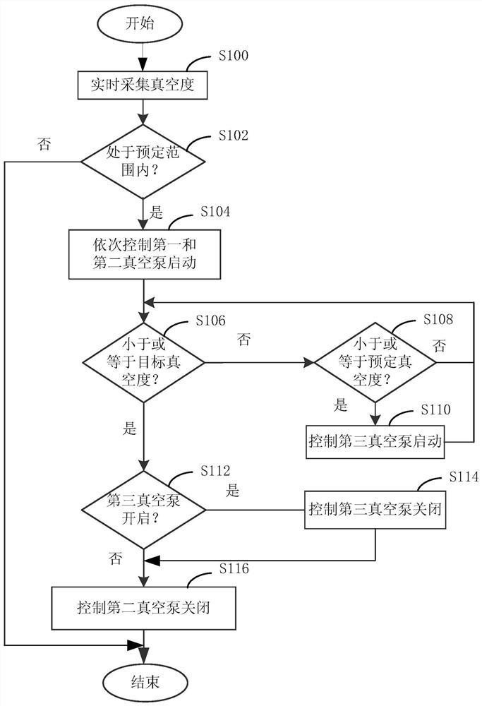
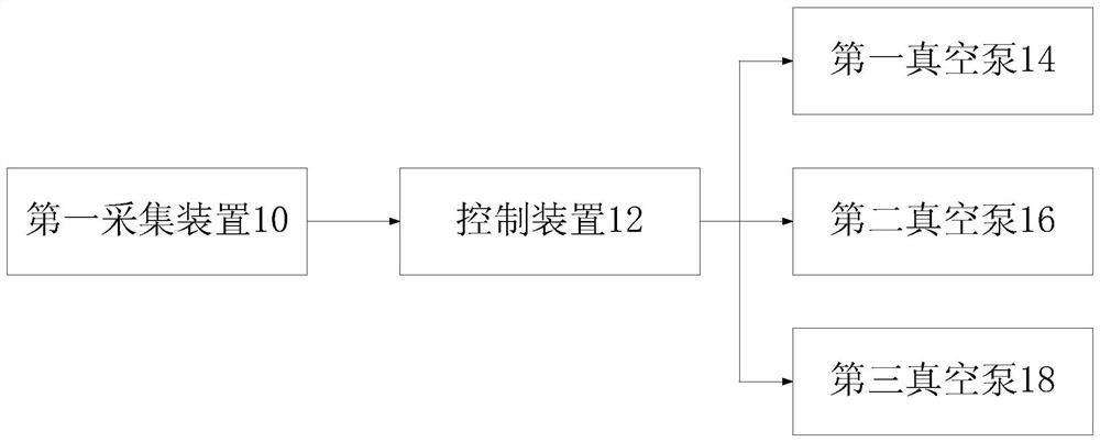
The invention relates to the technical field of vacuum environment control, and discloses a pipe tunnel vacuum control method and system. The method comprises the following steps: S100, collecting the vacuum degree of the separated part of two vacuum pipelines in real time; s102, whether the current vacuum degree is within a preset range or not is judged, if yes, the step S104 is executed, and if not, the process is ended; s104, a first vacuum pump is controlled to be started to execute vacuum pumping operation, and a second vacuum pump is controlled to be started to execute vacuum pumping operation after a preset time interval; s106, whether the current vacuum degree is smaller than or equal to the target vacuum degree or not is judged, if yes, the step S112 is executed, and if not, the step S108 is executed; s108, whether the current vacuum degree is smaller than or equal to the preset vacuum degree or not is judged, if yes, the step S110 is executed, and if not, the step S106 is executed; s110, a third vacuum pump is controlled to be started to execute vacuumizing operation, and the step S106 is executed again; s112, judging whether a third vacuum pump is in an open state or not, if yes, turning to S114, and if not, turning to S116; s114, controlling the third vacuum pump to be closed, and turning to S116; and S116, the second vacuum pump is controlled to be closed.

Description

technical field [0001] The invention relates to the technical field of vacuum environment control, in particular to a tube tunnel vacuum control method and system. Background technique [0002] The vacuum pipeline is the infrastructure for the operation of the maglev high-speed flying car with a speed of 1000km / h. The vacuum pipeline mainly includes the pipe beam structure, the basic support and the vacuum equipment system. The tube-beam structure is the main structure of the vacuum test bench, providing a container carrier with sufficient strength and excellent sealing performance; the basic support provides a load bearing for the container installation and controllable settlement; the vacuum equipment system includes a vacuum pump set, a re-pressure valve, and power supply equipment , its function is to provide functional equipment for the test platform to establish a vacuum, restore the atmosphere, and supply power to the vacuum environment. [0003] Due to the need to s...

Claims


Application Information

Patent Timeline
IPC IPC(8): F04B49/06F04B49/02F04B37/14F04B41/06B61B13/10
CPCF04B49/065F04B49/02F04B37/14F04B41/06B61B13/10
Inventor 毛凯张艳清金成日宋悦熙沈霄彬张国华沈胜兵
Owner HIWING TECH ACAD OF CASIC
Learn More