Worm and gear speed reducer

A worm gear, reducer technology, applied in mechanical equipment, gear lubrication/cooling, belts/chains/gears, etc., can solve the problems of reducing the life of the reducer, reducing the service life of the reducer, affecting the running accuracy, etc., to reduce the power The use of the power source, the guarantee of normal operation, and the effect of improving the transmission accuracy

Pending Publication Date: 2022-07-29
HANGZHOU YIDING TRANSMISSION MACHINERY
View PDF0 Cites 0 Cited by
  • Summary
  • Abstract
  • Description
  • Claims
  • Application Information

AI Technical Summary

Problems solved by technology

[0003] The worm gear and worm are prone to wear during the transmission process, resulting in the increase of the gap between the worm gear and worm, which affects the running accuracy. At the same time, the debris generated by the wear is easy to adhere to the surface of the worm gear and the worm, resulting in a high temperature between the worm gear and worm. Below the critical value, reducing the service life of the reducer
[0004] In view of the above-mentioned related technologies, the inventor believes that there are the following defects: in order to improve the stability of the reducer operation, lubricating oil will be provided inside the reducer to lubricate and cool the internal components, and the reducer should not be installed vertically as much as possible. Type installation, because when the reducer is installed vertically, the upper bearing cannot touch the lubricating oil in the box. After the reducer has been running for a long time, the lubrication performance of the bearing will deteriorate, resulting in easy necrosis of the bearing and reducing the life of the reducer.

Method used


Image

  • Worm and gear speed reducer
  • Worm and gear speed reducer
  • Worm and gear speed reducer

Examples


Embodiment Construction

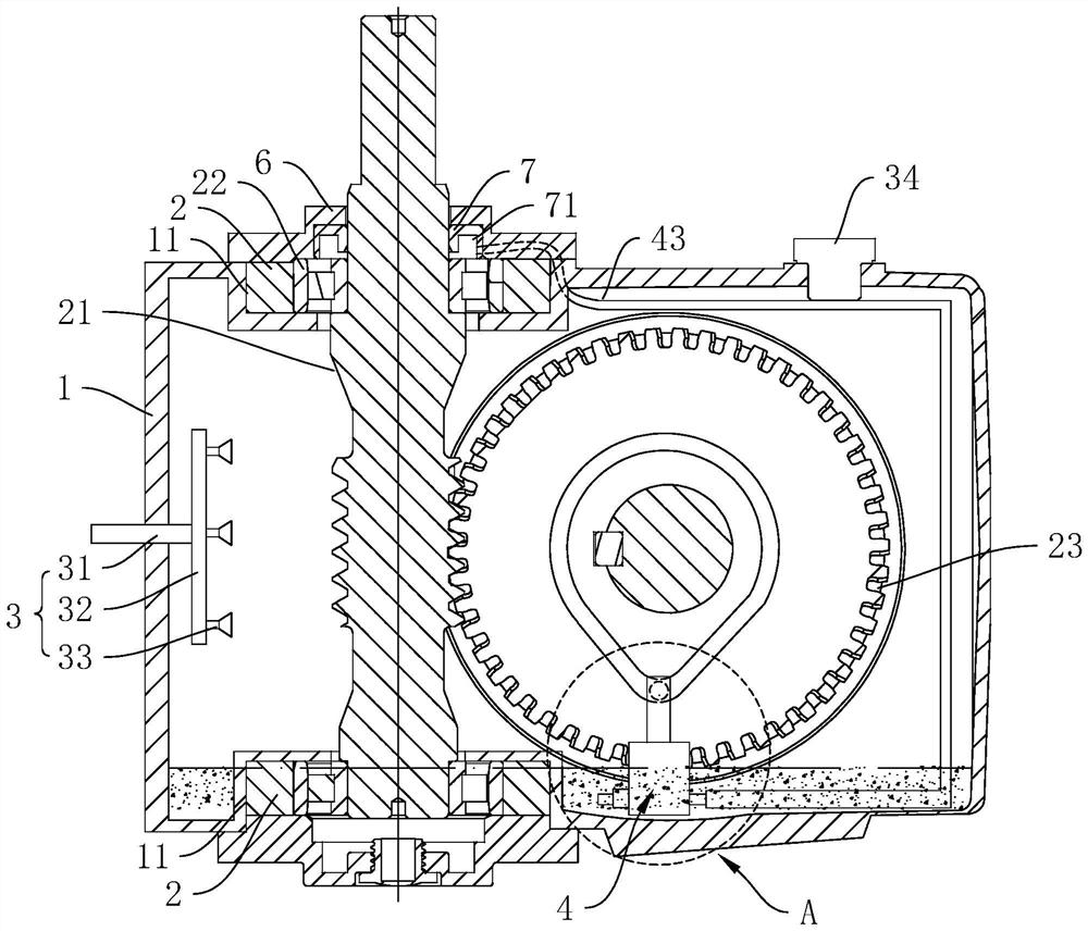
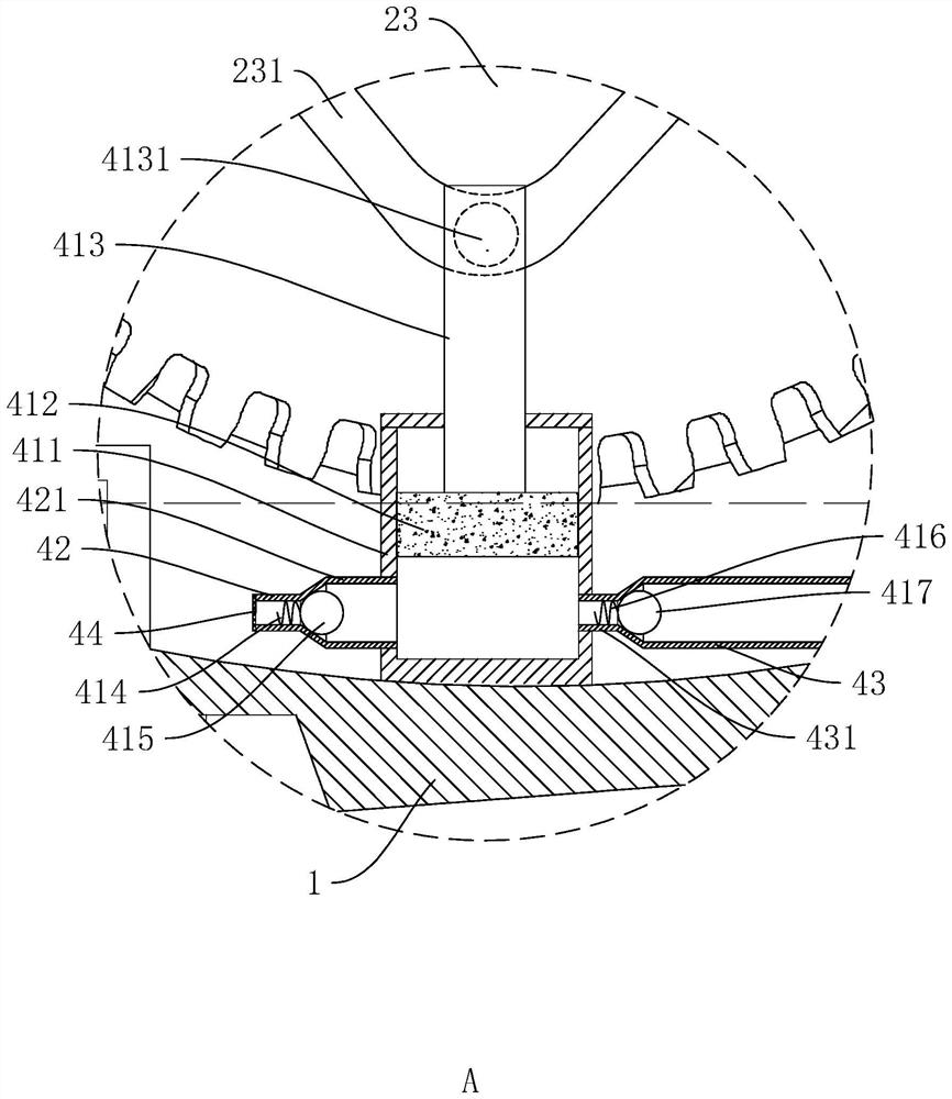
[0042] Attached to the following Figure 1-5 This application will be described in further detail.

[0043] The embodiment of the present application discloses a worm gear reducer. refer tofigure 1 , including a vertically installed box 1, the top and bottom of the box 1 are provided with mounting grooves 11, the bearing mounting seat 2 is installed in the mounting groove 11, and the bearing mounting seat 2 is provided with a worm 21, and the worm 21 and the bearing mounting seat A bearing 22 is connected between 2, and a worm wheel 23 meshing with the worm 21 is also arranged in the box body 1. The worm wheel 23 is rotatably connected with the side wall of the box body 1 through the output shaft. For the purging assembly 3, an oil supply device 4 for circulating oil is provided in the box 1.

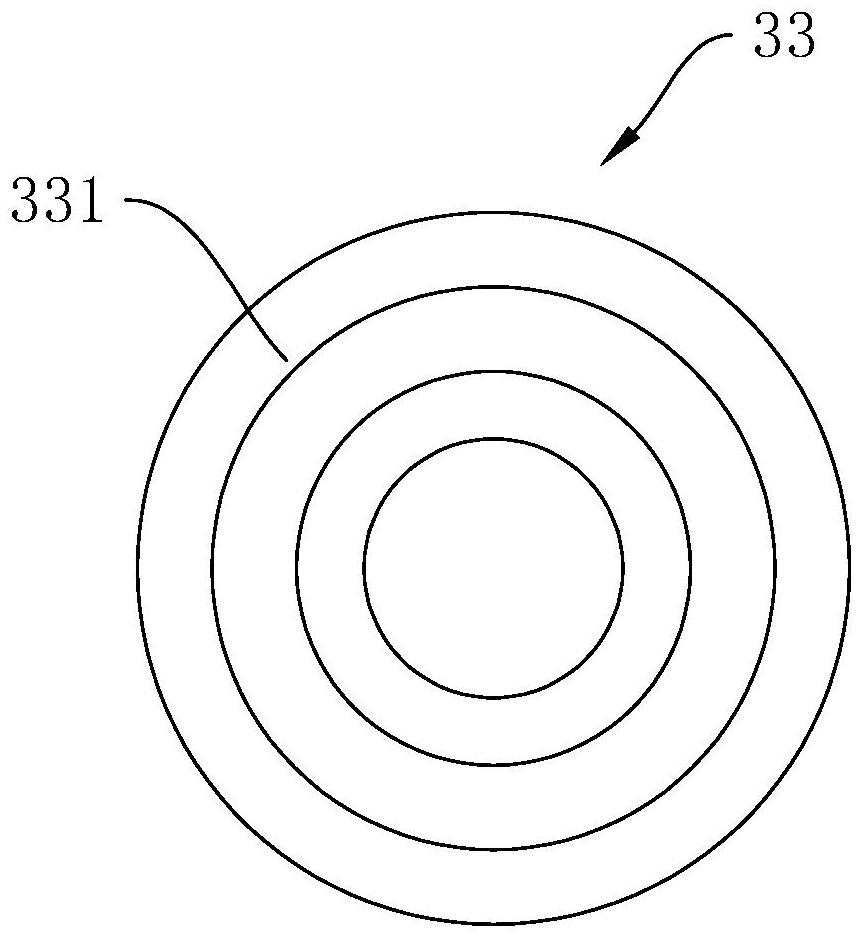
[0044] refer to figure 1 and figure 2 , the purging assembly 3 includes an air inlet main pipe 31, an air inlet branch pipe 32 and an air outlet 33. One end of the air inlet main p...


PUM


Abstract

The worm and gear speed reducer comprises a box body and bearing mounting seats, and the bearing mounting seats are fixed to the top and the bottom of the box body; the worm gear is meshed with the worm, the worm gear is rotationally connected with the box body, and the worm is rotationally connected with the bearing mounting seat; the air outlet end of the purging assembly faces the worm; the oil supply device comprises a piston assembly, an oil inlet pipe and an oil outlet pipe, the piston assembly is installed at the bottom of the inner side of the box body, the power end of the piston assembly is connected with the worm wheel, the oil inlet pipe is installed on one side of the piston assembly, and one end of the oil outlet pipe is connected with the piston assembly; the end, away from the piston assembly, of the oil outlet pipe extends into a bearing mounting base located on the top of the box body. According to the sweeping assembly, chippings generated in the transmission process of the worm and the worm wheel can be swept away, the influence of the chippings on transmission is reduced, and the transmission precision is improved.

Description

technical field [0001] The present application relates to the technical field of reducers, in particular to a worm gear reducer. Background technique [0002] The basic structure of the worm gear reducer is mainly composed of the transmission parts worm gear, shaft, bearing, box and its accessories. The main function of the worm gear and worm is to transmit the motion and power between the two staggered shafts. The main function of the bearing and the shaft is to transmit power, operate and improve efficiency. [0003] The worm gear and worm are prone to wear during the transmission process, which leads to the increase of the gap between the worm gear and the worm, which affects the running accuracy. At the same time, the debris generated by the wear is easily attached to the surface of the worm gear and the worm, resulting in the temperature between the worm gear and the worm being easily high. At the critical value, the service life of the reducer is reduced. [0004] In...

Claims


Application Information

Patent Timeline
Patent Type & Authority Applications(China)
IPC IPC(8): F16H57/04F16H57/039B08B5/02
CPCF16H57/0423F16H57/0434F16H57/0471F16H57/0498F16H57/0416F16H57/039B08B5/023
Inventor 张伟张景发
Owner HANGZHOU YIDING TRANSMISSION MACHINERY
Why Eureka
Try Eureka