Super high-rise concrete pouring quality control device

A control device, concrete technology, applied in the direction of measuring device, vibration suppression adjustment, spring/shock absorber, etc., can solve problems such as poor quality control of concrete pouring, and achieve the effect of improving the convenience of detection and reducing the intensity of operation

Pending Publication Date: 2022-07-29
THE FIRST CONSTR ENG COMPANY LTD OF CHINA CONSTR SECOND ENG BUREAU +2
0 Cites 0 Cited by

AI-Extracted Technical Summary

Problems solved by technology

[0005] Aiming at the deficiencies of the prior art, the present invention provides a control device for super ...

Method used

The upper end right side of base 1 is provided with adjusting frame 4, and the right end of adjusting frame 4 is provided with moving groove 5, and the upper end of adjusting frame 4 is provided with first motor 6 with respect to moving groove 5, and the first motor 6 The lower end is extended with a motor shaft and the lower end of the motor shaft is provided with a lead screw 21, the lead screw 21 is penetrated with a moving block 20, the moving block 20 is threaded with the lead screw 21, and the inner lower end of the moving groove 5 is provided with a bearing 22. ...

Abstract

The invention provides a control device for super high-rise concrete pouring quality, and relates to the technical field of super high-rise concrete pouring. The control device based on the super high-rise concrete pouring quality comprises a base and a protective groove frame, a second electric push rod is arranged at the left end of the interior of the protective groove frame, a rotating frame is arranged at one end of the second electric push rod, a rotating groove is formed in the right end of the rotating frame, and a second motor is arranged in the rotating groove. A motor shaft extends from one end of the second motor, a connecting rod is arranged at one end of the motor shaft, a supporting frame is arranged at the right end of the connecting rod, first electric push rods are arranged on the two sides of the lower end in the supporting frame, and a lifting plate is arranged at the upper ends of the first electric push rods; a concrete thickness detector is arranged in the middle of the upper end of the lifting plate, and a detection probe is arranged at the upper end of the concrete thickness detector and extends relative to the through opening. The device can be used for effectively detecting the quality.

Application Domain

Measurement devicesStands/trestles +1

Technology Topic

Motor shaftControl theory +3

Image

  • Super high-rise concrete pouring quality control device
  • Super high-rise concrete pouring quality control device
  • Super high-rise concrete pouring quality control device

Examples

  • Experimental program(1)

Example Embodiment

[0030] Example:
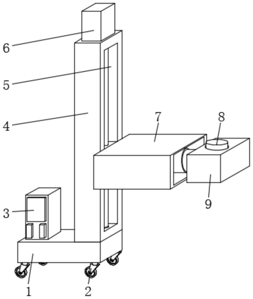
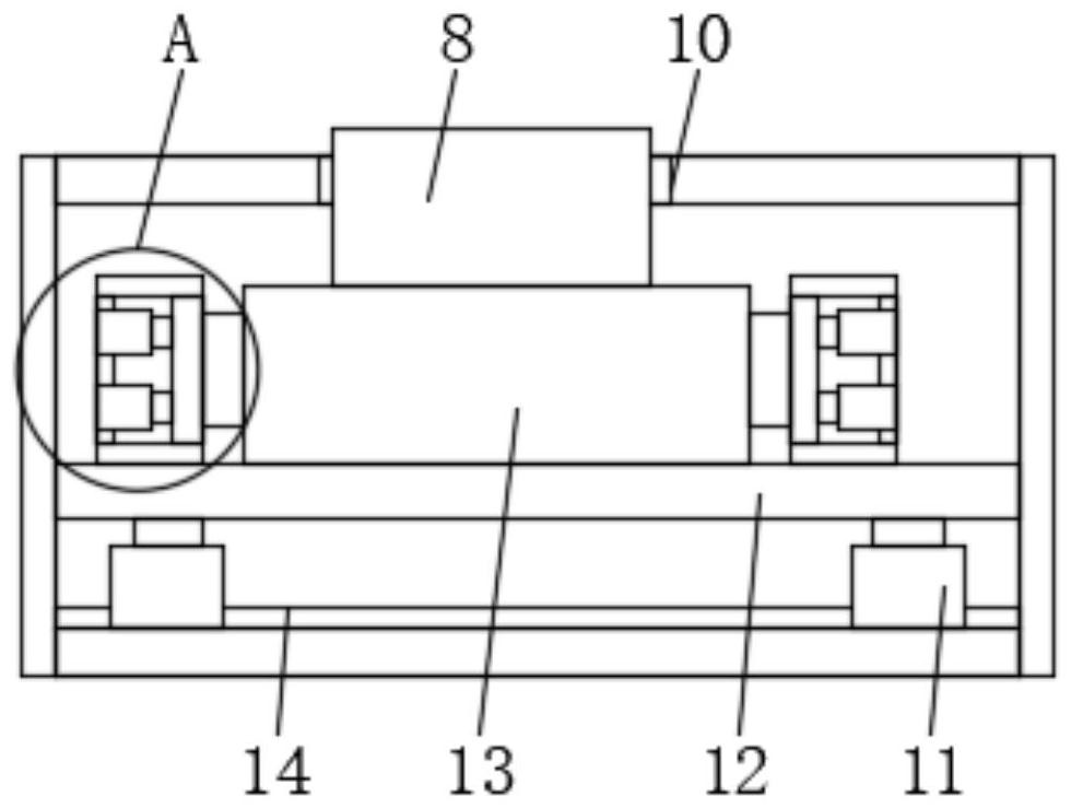
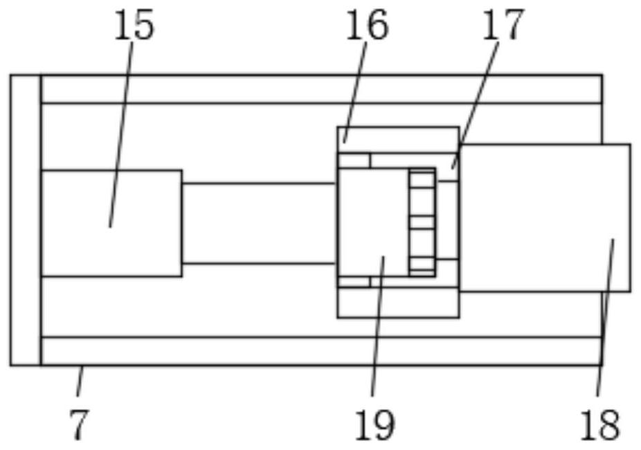
[0031] like Figure 1-6 As shown, the embodiment of the present invention provides a control device for the pouring quality of super high-rise concrete, including a base 1 and a protective groove frame 7, a control box 3 is provided on the left side of the upper end of the base 1, and a buffer groove 26 is provided at the lower end of the base 1, The inner upper end of the buffer groove 26 is provided with telescopic rods 23, the telescopic rods 23 are provided with a plurality of and are arranged at equal intervals, and the side of the telescopic rod 23 is provided with a mounting block 24, and the upper end of the mounting block 24 is connected with the inner upper end of the buffer groove 26, The lower end side of the telescopic rod 23 is provided with a spring 25, the lower end of the telescopic rod 23 is provided with a buffer block 27, and the lower end of the buffer block 27 is provided with a universal wheel 2, and the base 1 is conveniently moved and used through the universal wheel 2, And in the process of moving, the buffer block 27 is formed by the telescopic rod 23 and the spring 25 in the buffer groove 26 for buffer use, so as to form a buffer and stable support for the base 1;
[0032] An adjustment frame 4 is arranged on the right side of the upper end of the base 1, and a moving slot 5 is arranged at the right end of the adjustment frame 4. The upper end of the adjustment frame 4 and relative to the moving slot 5 are provided with a first motor 6, and the lower end of the first motor 6 extends with a The motor shaft and the lower end of the motor shaft are provided with a lead screw 21, the lead screw 21 is provided with a moving block 20, the moving block 20 is threadedly connected with the lead screw 21, the inner lower end of the moving groove 5 is provided with a bearing 22, and the inner sleeve of the bearing 22 is connected to the The lower end of the lead screw 21 is connected, the protective groove frame 7 is arranged on the right end of the adjusting frame 4, the left end of the protective groove frame 7 is connected with the right end of the moving block 20, and the lead screw 21 is driven to rotate by the first motor 6 at the adjusting frame 4, To adjust the use height of the protective groove frame 7 at the moving block 20, so as to detect and use the thickness and quality of concrete at different heights, and improve the convenience of control operations;
[0033] The protective groove of the protective groove frame 7 is arranged at the right end, the inner left end of the protective groove frame 7 is provided with a second electric push rod 15, one end of the second electric push rod 15 is provided with a turret 16, and the right end of the turret 16 is provided with a rotary groove 17. A second motor 19 is provided inside the rotating slot 17, one end of the second motor 19 is extended with a motor shaft and one end of the motor shaft is provided with a connecting rod 18, the right end of the connecting rod 18 is provided with a support frame 9, the support frame 9 can be Move to the inside of the protective groove frame 7, and adjust the left and right positions of the turret 16 through the second electric push rod 15, so as to facilitate the adjustment of the support frame 9 from the protective groove frame 7, and rotate the groove through the turning frame 16. The second motor 19 in 17 drives the connecting rod 18 to rotate to rotate the use angle of the support frame 9 to perform multi-angle detection and use;
[0034] A through port 10 is provided in the middle of the upper end of the support frame 9, a first electric push rod 11 is provided on both sides of the inner lower end of the support frame 9, and a connecting block 14 is provided on the side of the first electric push rod 11. The inner lower end of the support frame 9 is connected, the upper end of the first electric push rod 11 is provided with a lifting plate 12, and the middle of the upper end of the lifting plate 12 is provided with a concrete thickness detector 13, and the upper end of the concrete thickness detector 13 is opposite to the port 10. A detection probe 8 is extended, and the use height of the lifting plate 12 is adjusted through the first electric push rod 11 in the support frame 9, so that the detection probe 8 is adjusted from the port 10 for detection and use;
[0035] Limiting structures 28 are provided on both sides of the upper end of the lift plate 12 and opposite to the two sides of the concrete thickness detector 13. The limiting structure 28 includes a limiting frame 282. The opposite surfaces of the limiting frame 282 are provided with push grooves 281. The push grooves The interior of 281 is provided with a third electric push rod 284, one end of the third electric push rod 284 is provided with convex blocks 283 relative to both sides of the concrete thickness detector 13, and the limit frame 282 at the limit structure 28 pushes the groove 281 The inner third electric push rod 284 drives the convex block 283 to limit the position of the concrete thickness detector 13 .
[0036]Working principle: The first motor 6 at the adjustment frame 4 drives the lead screw 21 to rotate to adjust the height of the protective groove frame 7 at the moving block 20, so as to detect the thickness and quality of concrete at different heights. The push rod 15 is used to adjust the left and right positions of the turret 16, so as to facilitate the adjustment of the support frame 9 from the protective groove frame 7, and the second motor 19 in the rotating groove 17 at the turret 16 drives the connecting rod 18 to rotate to rotate. Rotate the use angle of the support frame 9 to perform multi-angle detection and use, and adjust the use height of the lifting plate 12 through the first electric push rod 11 in the support frame 9, so as to adjust the detection probe 8 from the port 10. , for detection use.

PUM

no PUM

Description & Claims & Application Information

We can also present the details of the Description, Claims and Application information to help users get a comprehensive understanding of the technical details of the patent, such as background art, summary of invention, brief description of drawings, description of embodiments, and other original content. On the other hand, users can also determine the specific scope of protection of the technology through the list of claims; as well as understand the changes in the life cycle of the technology with the presentation of the patent timeline. Login to view more.

Similar technology patents

AC socket wiring fault detection device

PendingCN113866686AImprove detection convenience
Owner:CRRC TANGSHAN CO LTD

Multipurpose sharpening machine

ActiveCN102672559Aeasy to operateReduce operating intensity
Owner:ZHEJIANG JIAHONG TOOL MFG CO LTD

Environment LED insecticidal lamp suitable for mountainous region agricultural planting

InactiveCN112400830AReduce operating intensityImprove support stability
Owner:陕西天秦农产品开发有限公司

Angle positioning method of gear and chain wheel

InactiveCN107553361AReduce operating intensityImprove pressing cycle time
Owner:THD ENG TECH LTD

Barrel-conveying vehicle

InactiveCN108891451Aimprove stabilityReduce operating intensity
Owner:曼胡默尔(天津)科技发展有限公司

Display screen detection jig

PendingCN112557395AImprove detection convenienceEnables Efficient Inspection Operations
Owner:BOE TECH GRP CO LTD +1

Six-knife cable stripper

PendingCN108711790AReduce operating intensityImprove operational efficiency
Owner:国网江苏省电力有限公司东海县供电分公司

Classification and recommendation of technical efficacy words

  • Improve detection convenience
  • Reduce operating intensity

Display screen detection jig

PendingCN112557395AImprove detection convenienceEnables Efficient Inspection Operations
Owner:BOE TECH GRP CO LTD +1

AC socket wiring fault detection device

PendingCN113866686AImprove detection convenience
Owner:CRRC TANGSHAN CO LTD

Aided driving system on rain or snow days and aided driving method

ActiveCN102866695AReduce operating intensityImprove driving safety
Owner:ZHEJIANG GEELY AUTOMOBILE RES INST CO LTD +1

Intelligent driving vehicle motorcade collaborative control system

PendingCN109318898AReduce operating intensity
Owner:山东派蒙机电技术有限公司

Method for separating protein adopting superparamagnetism silicon nanometer granule static adsorption

InactiveCN1876673Afast actingReduce operating intensity
Owner:HUNAN UNIV

Automatic steam heater and control method thereof

ActiveCN106667238AReduce operating intensityReduce labor costs
Owner:广东易爱云厨科技股份有限公司

Chinese prickly ash picking machine

InactiveCN108337999AImprove the efficiency of picking pepperReduce operating intensity
Owner:重庆市潼南区巨恒浩发种植股份合作社
Why Eureka
Try Eureka