Detection tool and turbocharger volute detection method

A technology of inspection fixtures and volutes, which is applied in the field of inspection of inspection fixtures and turbocharger volutes, can solve problems such as low detection efficiency, achieve the effect of simplifying inspection steps and improving inspection efficiency

Inactive Publication Date: 2022-07-29
KEHUA HLDG
View PDF6 Cites 0 Cited by
  • Summary
  • Abstract
  • Description
  • Claims
  • Application Information

AI Technical Summary

Problems solved by technology

[0004] The technical problem to be solved by the present invention is: to overcome the deficiencies of the prior art, to provide a inspection tool and a turbocharger volute detection method, to solve the current problem of the gap between the bushing hole in the turbocharger volute and the end surface of the exhaust valve. The problem of low efficiency of distance detection

Method used


Image

  • Detection tool and turbocharger volute detection method
  • Detection tool and turbocharger volute detection method
  • Detection tool and turbocharger volute detection method

Examples


Embodiment 1

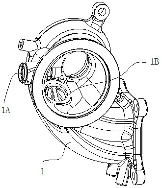
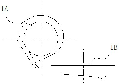
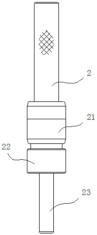
[0035] like Figure 1 to Figure 7 As shown, a checking tool includes a bushing reference shaft 2, including a centering shaft segment and a measuring shaft segment 23, the centering shaft segment is adapted to cooperate with the bushing hole 1A of the scroll casing 1, so as to make the centering The centerline of the shaft section coincides with the centerline of the bushing hole 1A, the centering shaft section coincides with the centerline of the measuring shaft section 23, and the outer diameter of the highest point on the measuring shaft section 23 is between the exhaust valve end face 1B. The distance between them is the distance to be measured; the dial indicator is suitable for matching with the outer diameter surface of the highest point of the measuring shaft section 23 and the exhaust valve end face 1B, so that the dial indicator 5 can display the measured value according to the displacement of the probe 51. , and compare the measured value with the calibration settin...

Embodiment 2

[0053] A method for detecting a turbocharger volute, using the inspection tool of the first embodiment, including the assembly of the bushing reference shaft 2: inserting the centering shaft section of the bushing reference shaft 2 into the bushing hole 1A of the volute 1, and inserting the The measuring shaft section 23 of the bushing reference shaft 2 extends to the side of the exhaust valve end face 1B, so that the center line of the measuring shaft section 23 coincides with the center line of the bushing hole 1A; The lower end surface is in contact with the low-level surface 61 of the calibration member 6, and the meter seat 3 is pressed down until the lower end surface of the shaft stop 31 is in contact with the high-level surface 62. At the same time, the upper end of the measuring rod 4 drives the measuring head 51 to move and drive the dial indicator. 5 work, set the position of the dial indicator 5 to the zero position at this time; specifically, first match the lower ...


PUM


Abstract

The invention relates to a testing fixture which comprises a bushing reference shaft, a centering shaft section and a measuring shaft section, the centering shaft section is suitable for being matched with a bushing hole of a volute so that the center line of the centering shaft section can coincide with the center line of the bushing hole, and the center line of the centering shaft section can coincide with the center line of the measuring shaft section. The distance between the outer diameter surface of the highest point on the measuring shaft section and the end surface of the waste gas valve is a distance to be measured; the dial indicator is used for detecting whether the volute is qualified or not. The turbocharger volute detection method adopts the detection tool, and comprises the following steps of: inserting the centering shaft section of the lining reference shaft into the lining hole of the volute; setting the position of the pointer of the dial indicator as a zero position; the dial indicator measuring tool judges whether the middle shell is qualified. The turbocharger volute inspection steps are simplified, and the inspection efficiency is improved.

Description

technical field [0001] The invention relates to a checking tool and a method for detecting a volute casing of a turbocharger. Background technique [0002] like figure 1 The shown turbocharger volute 1 has a bushing hole and an exhaust hole on the volute 1, and the exhaust hole forms the exhaust valve end face in the volute (the vertical structure between the exhaust valve end face 1B and the center line of the exhaust hole is formed). ), the exhaust valve end face 1B is used to install the exhaust valve, the bushing hole 1A and the exhaust gas hole are in a vertical staggered structure in the volute, that is, the centerline of the bushing hole 1A and the centerline of the exhaust gas hole are vertically staggered structure, The distance between the bushing hole 1A and the end face of the wastegate valve 1B is to control the tightness of the wastegate valve and the air chamber, so as to ensure that the turbocharger can continuously and stably boost the engine and improve th...

Claims


Application Information

Patent Timeline
Patent Type & Authority Applications(China)
IPC IPC(8): G01B5/00
CPCG01B5/003
Inventor 张瑜
Owner KEHUA HLDG
Why Eureka
Try Eureka