Steel strength detection device for building detection

A technology for strength detection and steel, applied in the field of steel strength detection devices for building inspection, can solve the problems of high labor cost, low practicability, lower detection efficiency, etc., and achieves high work efficiency, convenient operation and high practicability Effect

Inactive Publication Date: 2022-07-29
ANHUI UNIVERSITY OF ARCHITECTURE
View PDF0 Cites 3 Cited by
  • Summary
  • Abstract
  • Description
  • Claims
  • Application Information

AI Technical Summary

Problems solved by technology

[0003] Traditional inspection devices generally use heavy objects to hit the steel. After the impact is completed, the deformation of the steel is manually observed and measured. Although this method can obtain the measurement results of the steel, it requires a lot of labor in actual use. The time for observation and measurement reduces the detection efficiency, and the detection device cannot automatically screen out unqualified items, so the practicability is not high

Method used


Image

  • Steel strength detection device for building detection
  • Steel strength detection device for building detection
  • Steel strength detection device for building detection

Examples


Embodiment 1

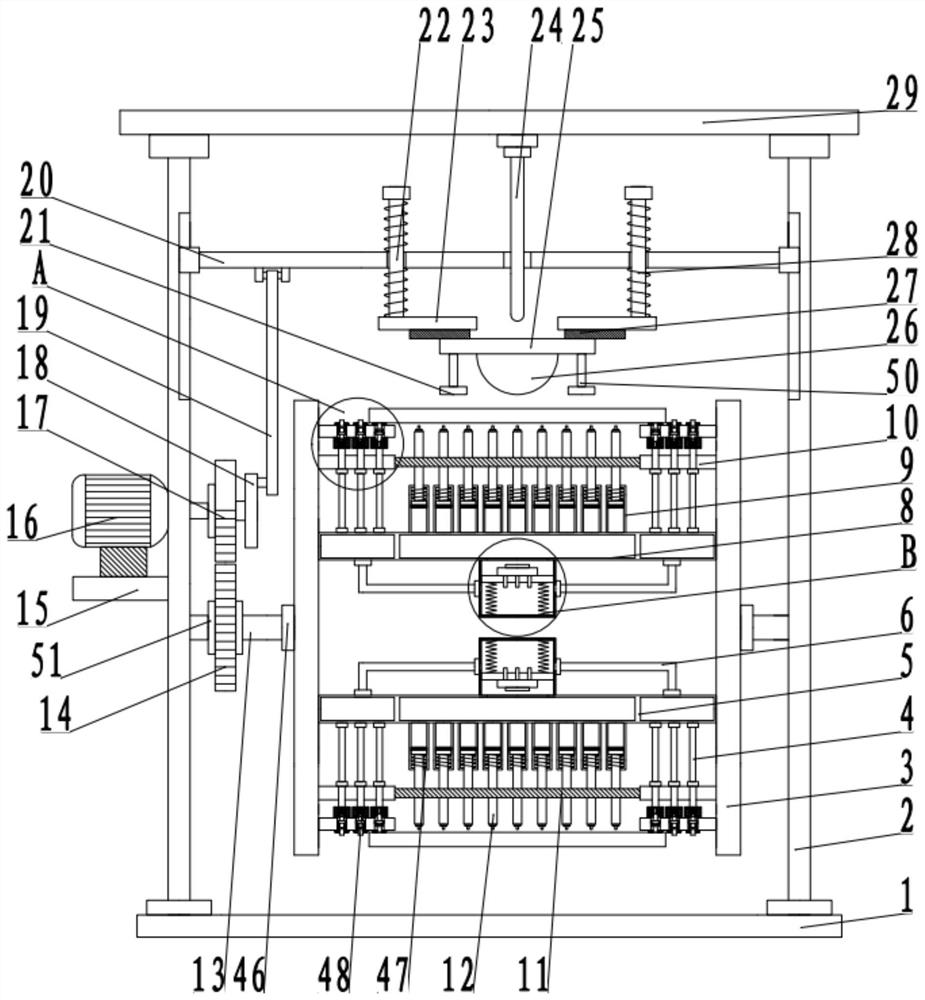
[0026] see Figure 1-5 , a steel strength detection device for building inspection, comprising a bottom plate 1, and also includes: a surrounding plate 2 fixedly arranged on both sides of the bottom plate 1, the top of the surrounding plate 2 is fixedly connected to the top plate 29; a feeding mechanism 46 arranged between the surrounding plates 2 , including the installation column 13, the installation column 13 is rotatably connected with the enclosure plate 2, one side of the installation column 13 is fixedly connected to the installation plate 3, the pressure divider 8 is fixedly connected between the installation plates 3, and both sides of the pressure divider 8 are fixedly connected. The baffle 5, the side wall of the mounting plate 3 is fixedly connected to the fixing rod 10, the fixed rod 10 is fixedly provided with an air guide 4, and the air guide 4 is fixedly connected with the partial pressure cylinder 8, and the installation plate 3 on one side of the air guide 4 ...

Embodiment 2

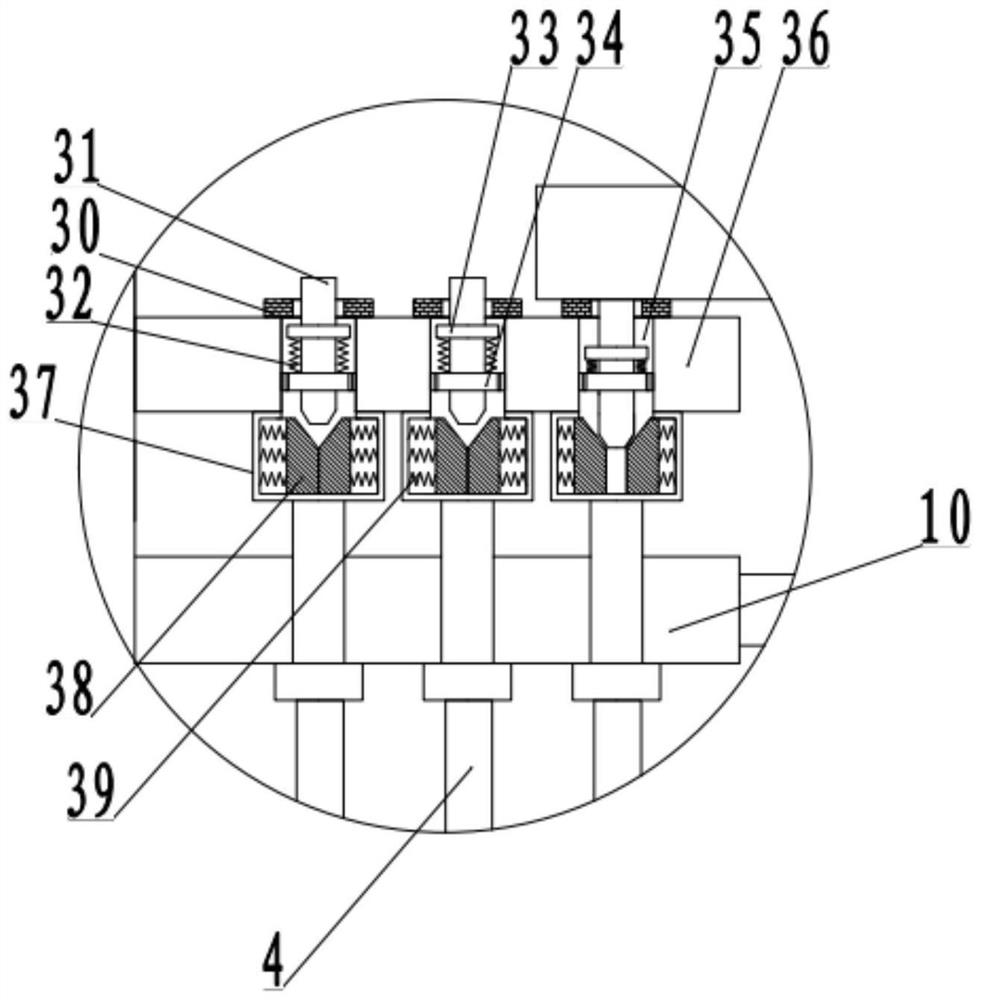
[0029] see Figure 1-5 , the other content of this embodiment is the same as that of Embodiment 1, the difference is that: the valve assembly 48 includes a mounting arm 36, the mounting arm 36 is fixedly connected with the mounting plate 3, the mounting arm 36 is provided with a through slot 35, and the through slot 35 A venting block 34 is fixedly arranged inside, the venting block 34 is fixedly arranged in the through groove 35, the venting block 34 slides through and sets a valve column 31, the valve column 31 is fixedly sleeved with the installation sleeve 33, the installation sleeve 33 and the ventilation block 34. The reset member 32 is fixedly connected between.

[0030]The mounting arm 36 above the through slot 35 is fixedly connected to the sealing ring 30 , the bottom of the mounting arm 36 below the through slot 35 is fixedly connected to the mounting shell 37 , the inner side wall of the mounting shell 37 is fixedly connected to the telescopic piece 39 , and one si...


PUM


Abstract

The invention discloses a steel strength detection device for building detection, and relates to the technical field of building detection, the steel strength detection device comprises a bottom plate, and also comprises surrounding plates fixedly arranged on two sides of the bottom plate, and the tops of the surrounding plates are fixedly connected with a top plate; the feeding mechanism is arranged between the surrounding plates and comprises a mounting column, the mounting column is rotationally connected with the surrounding plates, one side of the mounting column is fixedly connected with a mounting disc, a partial pressure cylinder is fixedly connected between the mounting discs, the two sides of the interior of the partial pressure cylinder are fixedly connected with partition plates, and a piston assembly is arranged on the partial pressure cylinder on one side of a limiting rod and penetrates through the limiting rod; the detection mechanism is arranged on one side of the mounting disc and comprises a movable rod, the two sides of the movable rod are in sliding connection with a surrounding plate, an impact assembly is arranged below the movable rod, a driving assembly is arranged on one side of the surrounding plate, and the driving assembly is arranged on the other side of the surrounding plate. The driving assembly drives the movable rod to move up and down in a reciprocating mode to achieve collision detection of objects.

Description

technical field [0001] The invention relates to the technical field of building detection, in particular to a steel strength detection device for building detection. Background technique [0002] With the rapid development of my country's construction level in recent years, my country's construction industry level has been far ahead of the world's average level. In the construction industry, construction steel bars, cement, steel, etc. are all commonly used materials for construction. Construction steel materials can usually be divided into steel for steel structures and steel for reinforced concrete structures. Steel for steel structure mainly includes ordinary carbon structural steel and low alloy structural steel. The varieties are section steel, steel pipe and steel bar. There are angle steel, I-beam and channel steel in section steel. [0003] The traditional inspection device generally uses heavy objects to impact the steel. After the impact is completed, the deform...

Claims


Application Information

Patent Timeline
Patent Type & Authority Applications(China)
IPC IPC(8): G01N3/303G01N3/04G01N3/02
CPCG01N3/303G01N3/04G01N3/02G01N2203/0019G01N2203/0032G01N2203/0075G01N2203/0411
Inventor 何玮刘越
Owner ANHUI UNIVERSITY OF ARCHITECTURE
Why Eureka
Try Eureka