
High-precision schlieren system light path adjusting device and use method thereof

An optical path adjustment, high-precision technology, applied in the field of power machinery, can solve problems such as influence, and achieve the effect of high-precision schlieren system, low cost, and high reliability

Pending Publication Date: 2022-07-29
HARBIN ENG UNIV
View PDF14 Cites 0 Cited by
  • Summary
  • Abstract
  • Description
  • Claims
  • Application Information

AI Technical Summary

Problems solved by technology

[0005] This invention proposes a high-precision schlieren system optical path adjustment device and its use method, so as to avoid the installation of additional devices on the mirror surface in the optical path setting to realize light correction , the installation of the device will affect the overall optical path to a certain extent

Method used


Image

  • High-precision schlieren system light path adjusting device and use method thereof
  • High-precision schlieren system light path adjusting device and use method thereof
  • High-precision schlieren system light path adjusting device and use method thereof

Examples


Embodiment Construction

[0027] The technical solutions in the embodiments of the present invention will be clearly and completely described below with reference to the accompanying drawings in the embodiments of the present invention. Obviously, the described embodiments are only a part of the embodiments of the present invention, but not all of the embodiments. Based on the embodiments of the present invention, all other embodiments obtained by those of ordinary skill in the art without creative efforts shall fall within the protection scope of the present invention.

[0028] The invention is mainly aimed at the improvement of the optical path, and researches and invents without involving light, thereby realizing the improvement of the overall precision, and proposes a high-precision schlieren system.

[0029] The Z-shaped optical path converts the incident light into parallel light through the mirror surface, and the parallel light passes through the detection area to measure relevant information an...


PUM


Abstract

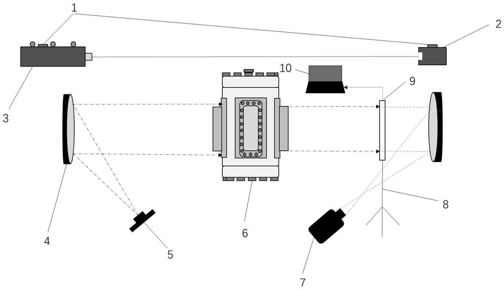
The invention discloses a high-precision schlieren system light path adjusting device and a use method thereof, and belongs to the field of power machinery. A high-precision schlieren system light path adjusting device is characterized in that a laser emitter and a laser receiver are horizontally arranged, the laser emitter emits horizontal laser, the laser receiver receives the horizontal laser, and a constant volume bomb is parallel to the horizontal laser; wherein one schlieren instrument, the constant volume bomb, the optical sensor and the other schlieren instrument are sequentially arranged in the direction parallel to the horizontal laser, an incidence window and a perspective window of the constant volume bomb correspond to one schlieren instrument and the optical sensor respectively, the light source irradiates one schlieren instrument, and the camera corresponds to the other schlieren instrument. The signal output end of the optical sensor is connected with the signal input end of the computer. According to the invention, the precision problem of the schlieren method is solved, the optical sensor can be moved without changing the whole optical path, and the whole is not affected. The system is low in cost, high in reliability, convenient and high in overall perfection degree.

Description

technical field [0001] The invention relates to an optical path adjusting device of a high-precision schlieren system and a method for using the same, belonging to the field of power machinery. Background technique [0002] In the research field of internal combustion engine visualization technology, the two most commonly used methods are MIE scattering method and schlieren method. The schlieren method has important visualization applications because it can display the invisible flow field inside the constant volume bomb. significance. For the study of schlieren method, there are many kinds of optical paths in schlieren method, such as Z-type optical path, T-type optical path and BOS method optical path. [0003] At present, in the process of visualization of internal combustion engines, the requirements for accuracy are getting higher and higher, and the realization of accurate information collection is the highlight of the current visualization technology research process...

Claims


Application Information

Patent Timeline
IPC IPC(8): G02B27/30G02B27/62F16M11/32G01M15/04G01M15/02
CPCG02B27/30G02B27/62F16M11/32G01M15/04G01M15/02
Inventor 董全樊旭倪佐王定文夏天峰
Owner HARBIN ENG UNIV
Learn More