Universal rubberizing cover plate jig

A cover and jig technology, applied in the field of lighting, can solve the problems of poor versatility of jigs

Pending Publication Date: 2022-07-29
重庆博硕光电有限公司
View PDF0 Cites 0 Cited by
  • Summary
  • Abstract
  • Description
  • Claims
  • Application Information

AI Technical Summary

Problems solved by technology

[0004] The purpose of the present invention is to solve the problem of poor versatility of existing fi

Method used


Image

  • Universal rubberizing cover plate jig
  • Universal rubberizing cover plate jig
  • Universal rubberizing cover plate jig

Examples


Embodiment Construction

[0031] The technical solutions in the embodiments of the present invention will be clearly and completely described below with reference to the accompanying drawings in the embodiments of the present invention. Obviously, the described embodiments are only a part of the embodiments of the present invention, rather than all the embodiments. Based on the embodiments of the present invention, all other embodiments obtained by those of ordinary skill in the art without creative efforts shall fall within the protection scope of the present invention.

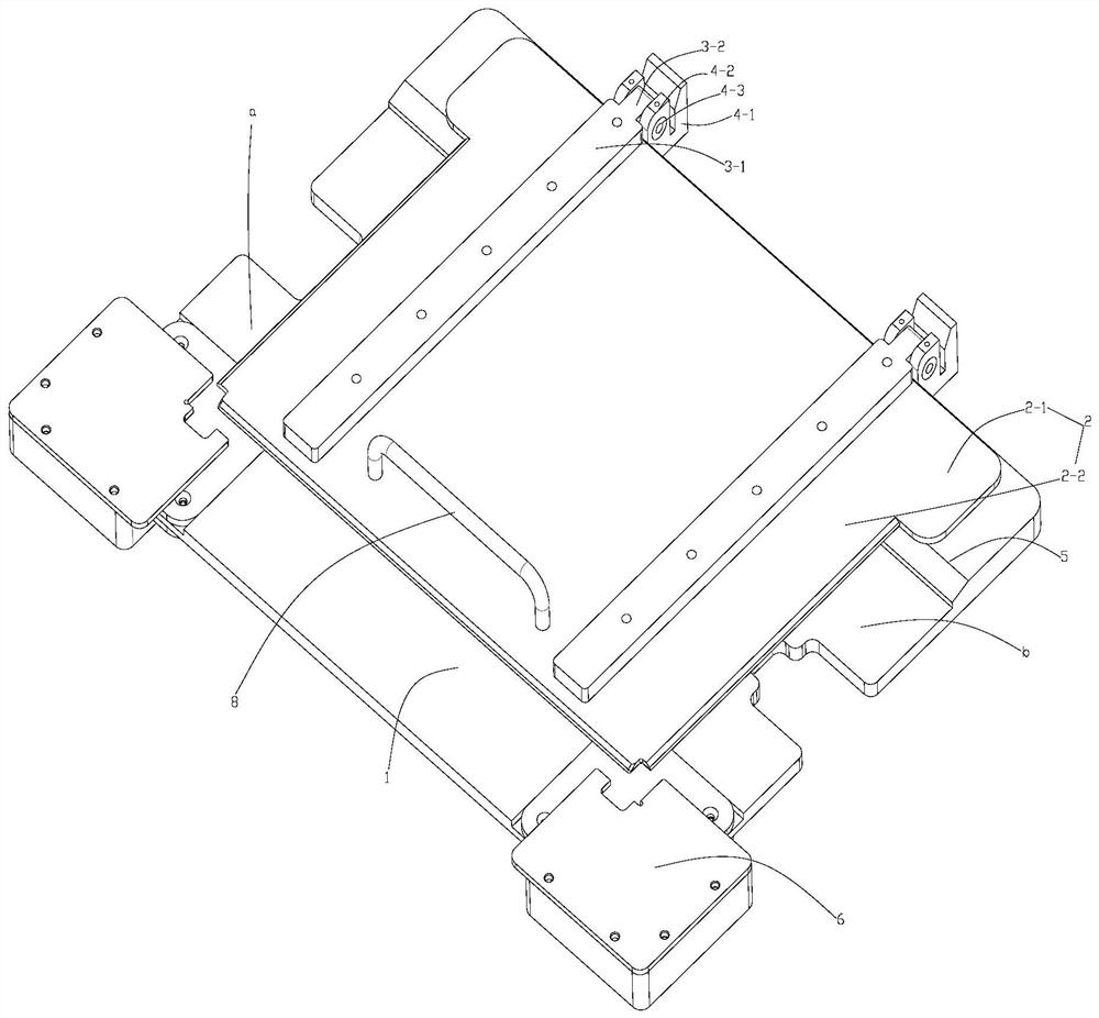
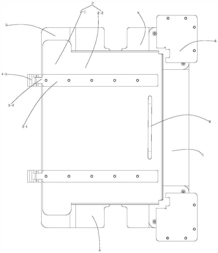
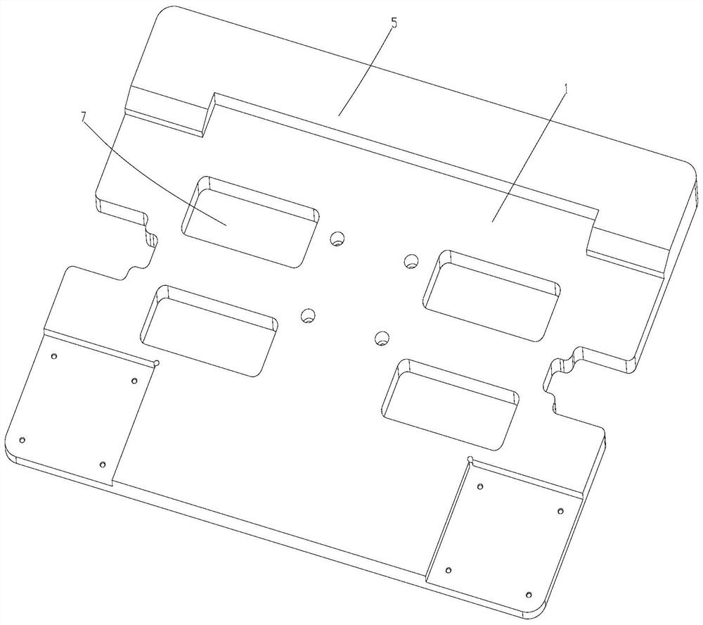
[0032] like Figure 1 to Figure 3 shown:

[0033] It includes a bottom plate 1, a cover plate 2 and a hinge seat 4-1, the bottom plate 1 is a rectangular structure, the bottom of the bottom plate 1 is fixedly connected to the rotating disk, and the cover plate 2 is hinged on the side surface of the bottom plate 1 through the hinge seat 4-1.

[0034] Two hinge bases 4 - 1 are welded side by side on the same side of the base plate 1 ,...


PUM


Abstract

The invention relates to a universal rubberizing cover plate jig, aims to solve the problem of poor universality of an existing jig, and provides a universal rubberizing cover plate jig which comprises a bottom plate and a cover plate, a strip-shaped placement area is arranged in the middle of the bottom plate, and the cover plate is hinged to one side of the bottom plate. When the cover plate covers the bottom plate, the cover plate covers part of the strip-shaped placing area; and the uncovered part of the strip-shaped placing area is a bonding area. The universal rubberizing cover plate jig improves the universality of the jig. And membrane pollution is reduced by improving the position of the cover plate.

Description

technical field [0001] The invention relates to the field of lighting, in particular to a universal glue sticking cover plate jig. Background technique [0002] In the early stage, the operator manually attaches the shading tape to the shading tape of the backlight product using a special machine type glue jig. [0003] At present, this method has the following problems: there are many fixtures to be purchased, the cost is high, and the space is occupied. When the temporary wire body is produced, the jig cannot be used, which easily leads to the contamination of the diaphragm. SUMMARY OF THE INVENTION [0004] The purpose of the present invention is to solve the problem of poor versatility of the existing jig, and propose a general-purpose glue cover plate jig, and the specific technical scheme is as follows: [0005] Universal glue cover plate fixture, which is characterized by: [0006] Including bottom plate and cover plate; [0007] A strip-shaped placement area is...

Claims


Application Information

Patent Timeline
IPC IPC(8): G02F1/13B29C63/02
CPCG02F1/13G02F1/1303B29C63/02
Inventor 谭金寅王勇左仁旭黄禹
Owner 重庆博硕光电有限公司
Why Eureka
Try Eureka