Retractor with thyroid retractor head structure
A thyroid and retractor technology, applied in the field of retractors, can solve the problems of not installing the retractor, reducing work efficiency, and different pulling speeds, so as to facilitate other operations, improve work efficiency, and reduce work burden Effect
- Summary
- Abstract
- Description
- Claims
- Application Information
AI Technical Summary
Problems solved by technology
Method used
Image

Examples
Embodiment 1
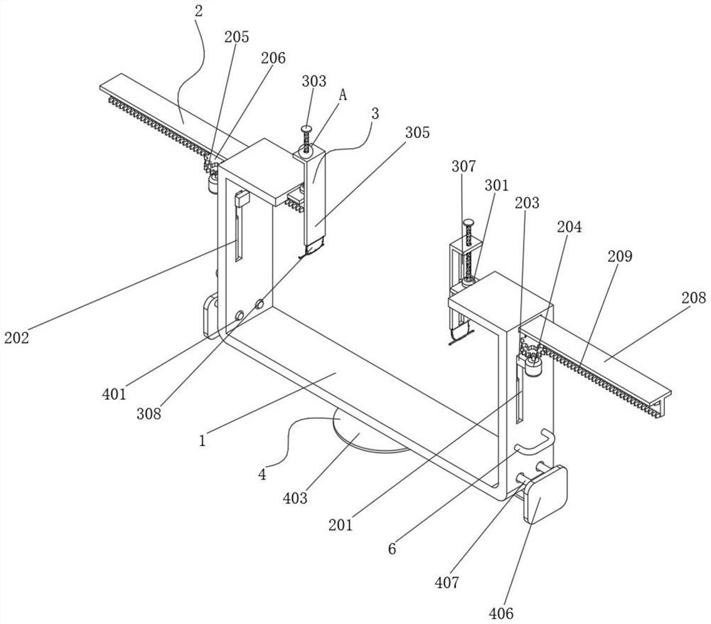
[0027] see figure 1 and Figure 5 , the present invention provides a technical scheme: a retractor with a thyroid retractor head structure, comprising a bracket body 1, a moving assembly 2, a lifting assembly 3 and an installation assembly 4, and a movable assembly is fixed on the top inner wall of the bracket body 1 2, the lifting assembly 3 is fixed on the top outer wall of the bracket main body 1, the mounting assembly 4 is fixed on the bottom outer wall of the bracket main body 1; the thyroid retractor head 5 is fixedly connected to the bottom outer wall of one side of the retractor 308, which can The skin, subcutaneous tissue, muscles and fascia are opened; handles 6 are welded and fixed on both outer walls of the bracket main body 1, which facilitates the bracket main body 1 to get to the designated position and improves the moving effect;
[0028] The moving assembly 2 includes a lifting slot 201, an air cylinder 202, a lifting block 203, a first motor 204, a first gea...
Embodiment 2
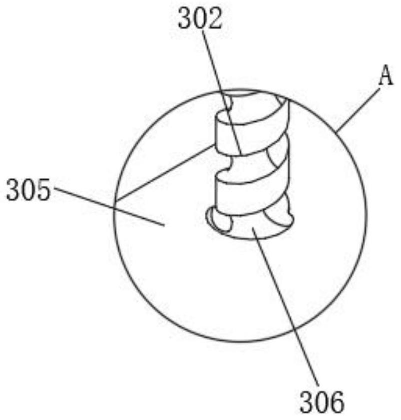
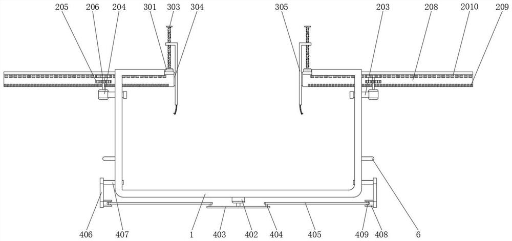
[0031] see figure 2 and Figure 4 , the lifting assembly 3 includes a second motor 301, a threaded rod 302, a baffle plate 303, a sliding block 304, a lifting plate 305, a threaded hole 306, a second sliding groove 307 and a retractor 308, and one end of the T-shaped sliding plate 208 is welded on the outer wall A sliding block 304 is fixed, a lifting plate 305 is symmetrically installed on one inner wall of the bracket main body 1, a second chute 307 is opened on one inner wall of the lifting plate 305 corresponding to the sliding block 304, and the bottom end outer wall of the lifting plate 305 is welded on the outer wall. A retractor 308 is fixed, a second motor 301 is inlaid on the top inner wall of the T-shaped sliding plate 208, a threaded rod 302 is installed on the top outer wall of the T-shaped sliding plate 208, and the top end of the output shaft of the second motor 301 is fixed to the thread On the outer wall of the rod 302, the top inner wall of the lifting plat...
Embodiment 3
[0034] see image 3 , the mounting assembly 4 includes a guide hole 401, a third motor 402, a rotating wheel 403, a first rotating shaft 404, a rotating plate 405, a connecting plate 406, a limit rod 407, an ear block 408 and a second rotating shaft 409. A connecting plate 406 is installed on both the side and outer walls. Limiting rods 407 are symmetrically welded and fixed on one outer wall of the connecting plate 406 . Guide holes 401 are distributed on the inner walls of the bracket body 1 corresponding to the limiting rods 407 . An ear block 408 is symmetrically welded and fixed on the outer wall of one side, a rotating plate 405 is installed on the outside between the ear blocks 408, and a second rotating shaft 409 is fixedly connected to the outer walls of both sides of the rotating plate 405, and the other end of the second rotating shaft 409 It is rotatably connected to the inner wall of the ear block 408, the third motor 402 is inlaid on the inner wall of the bottom ...
PUM
 Abstract
Description
Claims
Application Information
 - R&D
- Intellectual Property
- Life Sciences
- Materials
- Tech Scout
- Unparalleled Data Quality
- Higher Quality Content
- 60% Fewer Hallucinations
Browse by: Latest US Patents, China's latest patents, Technical Efficacy Thesaurus, Application Domain, Technology Topic, Popular Technical Reports.
© 2025 PatSnap. All rights reserved.Legal|Privacy policy|Modern Slavery Act Transparency Statement|Sitemap|About US| Contact US: help@patsnap.com