Grinding and polishing device for bars and machining equipment

A polishing device and bar technology, which is applied in grinding/polishing equipment, metal processing equipment, and machine tools designed for grinding the rotating surface of workpieces, etc., can solve the problem of unstable working position of grinding head, complicated transmission device, and low operating efficiency And other issues

Pending Publication Date: 2022-08-02
BAOSTEEL SPECIAL STEEL SHAOGUAN CO LTD
View PDF12 Cites 0 Cited by
  • Summary
  • Abstract
  • Description
  • Claims
  • Application Information

AI Technical Summary

Problems solved by technology

One is the working method of stripping first and then calendering and using grinder grinding equipment. The disadvantages are: the transmission device is complicated and the operation requirements are high. When using these equipment to grind and polish rods When processing materials, it generally requires careful and cumbersome operations and observations, so it is laborious and laborious, and the operating efficiency is low, which is not conducive to the improvement of production efficiency.
[0003] The other is to use the grinder grinding method to mainly rely on the vertical and axial movement of the grinding head for grinding. Its disadvantages are: the power device of the grinding head needs to move, resulting in unstable working position of the grinding head, and the axial movement of the bar is related to the The rotation speed is not easy to match, resulting in poor grinding ability of the bar surface, large roundness size error, and high energy consumption
[0004] The grinding process of the bar in the prior art has the problems of poor grinding ability and low operating efficiency

Method used


Image

  • Grinding and polishing device for bars and machining equipment
  • Grinding and polishing device for bars and machining equipment
  • Grinding and polishing device for bars and machining equipment

Examples


Embodiment Construction

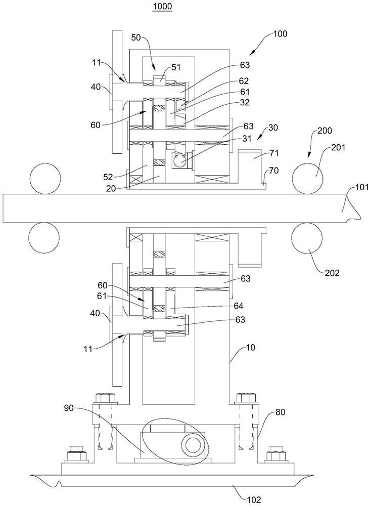
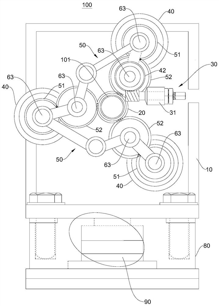
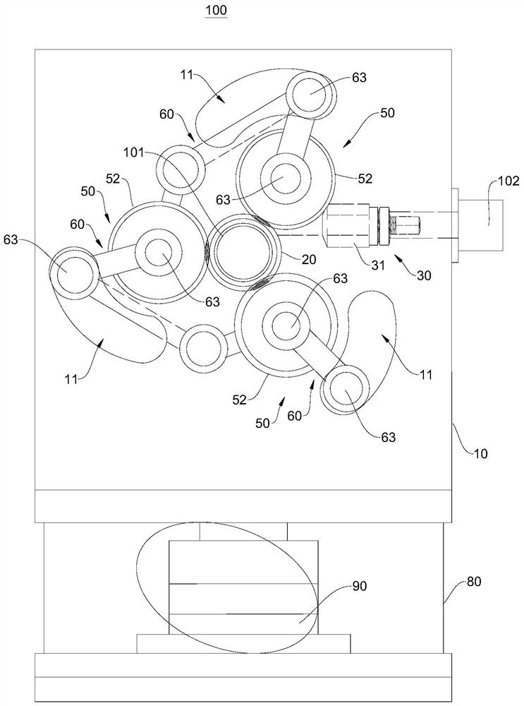
[0030] In order to make the purposes, technical solutions and advantages of the embodiments of the present invention clearer, the technical solutions in the embodiments of the present invention will be clearly and completely described below with reference to the accompanying drawings in the embodiments of the present invention. Obviously, the described embodiments These are some embodiments of the present invention, but not all embodiments. The components of the embodiments of the invention generally described and illustrated in the drawings herein may be arranged and designed in a variety of different configurations.

[0031] Thus, the following detailed description of the embodiments of the invention provided in the accompanying drawings is not intended to limit the scope of the invention as claimed, but is merely representative of selected embodiments of the invention. Based on the embodiments of the present invention, all other embodiments obtained by those of ordinary ski...


PUM


Abstract

The embodiment of the invention provides a grinding and polishing device for a bar and machining equipment, and relates to the field of metal machining equipment. The grinding and polishing device for the bar comprises a transmission box body, a transmission gear, a driving part, a plurality of grinding heads, a plurality of transmission parts and a plurality of connecting rods, the transmission gear, the driving part, the grinding heads, the transmission parts and the connecting rods are all arranged in the transmission box body, and the transmission gear is used for being arranged on the bar in a sleeving mode. The multiple grinding heads and the multiple transmission parts are arranged in the circumferential direction of the transmission gear at intervals, the number of the grinding heads is the same as that of the transmission parts, one grinding head is connected with one transmission part, every two adjacent transmission parts are connected through a connecting rod, all the transmission parts are meshed with the transmission gear, and the driving part is connected with one transmission part. And the transmission parts are used for driving the grinding heads to rotate under the driving of the driving part, and meanwhile, the other transmission parts are driven by the connecting rods to be linked together, so that all the grinding heads are driven to move towards the direction close to the bar until all the grinding heads are in contact with the bar.

Description

technical field [0001] The invention relates to the field of metal processing equipment, in particular to a grinding and polishing device and processing equipment for bars. Background technique [0002] In the process of bar rolling or straightening, the outer surface of the round steel will be more or less scratched, cracked, burrs and dimensional errors. In order to ensure the outer surface quality and dimensional accuracy of the bar, the finishing The engineering department needs to grind and polish the bars. At present, in the production process of grinding the outer surface of the bar, two methods are usually used for grinding. One is to use the equipment such as stripping first and then grinding and grinding with a grinder. The use of first stripping and then grinding has the disadvantage that the transmission device is complex and the operation requirements are high. When using these equipment to grind the polishing rod When the material is used, it generally requir...

Claims


Application Information

Patent Timeline
IPC IPC(8): B24B5/04B24B27/00B24B41/06
CPCB24B5/04B24B27/0076B24B41/067Y02P70/10
Inventor 杨家满胡占民廖子东潘电营刘振华戴坚辉温清洪龙建勇吴建成丘相林
Owner BAOSTEEL SPECIAL STEEL SHAOGUAN CO LTD
Why Eureka
Try Eureka