
Marking card for marking position of metallographic inlay sample and use method of marking card

A technology of marking card and metallography, which is applied in the preparation, sampling, measuring device and other directions of test samples, can solve the problems of deviation of grinding and polishing depth from the actual value, the inclination of grinding and polishing surface is heavy, and the manufacturing process is difficult, so as to reduce grinding and polishing. Casting difficulty, low wear resistance, good thermal stability

Pending Publication Date: 2022-02-25
CHINA HANGFA GUIZHOU LIYANG AVIATION POWER CO LTD
View PDF10 Cites 0 Cited by
  • Summary
  • Abstract
  • Description
  • Claims
  • Application Information

AI Technical Summary

Problems solved by technology

Traditional grinding and polishing methods and marking tools need to obtain the grinding and polishing depth of the sample through measurement and geometric relationship conversion. The premise of satisfying these conversion relationships is that the grinding and polishing surface is at the same level, and the flatness of the grinding and polishing surface of the sample is extremely demanding. High, if the sample maker lacks technology or experience, the grinding and polishing surface will be inclined heavily, and the grinding and polishing depth value converted by the traditional method or marking tool will seriously deviate from the actual value, resulting in the failure of the test
Traditional marking tools are all made of metal, the manufacturing process is relatively difficult and the cost is high
Moreover, the metal material has high hardness and wear resistance, which increases the difficulty of the sample preparation grinding and polishing process.

Method used


Image

  • Marking card for marking position of metallographic inlay sample and use method of marking card
  • Marking card for marking position of metallographic inlay sample and use method of marking card

Examples


Embodiment Construction

[0028] The following will clearly and completely describe the technical solutions in the embodiments of the present invention with reference to the accompanying drawings in the embodiments of the present invention. Obviously, the described embodiments are only part of the embodiments of the present invention, not all of them. Based on the embodiments of the present invention, all other embodiments obtained by persons of ordinary skill in the art without creative efforts fall within the protection scope of the present invention.

[0029] It should be noted that all directional indications (such as up, down, left, right, front, back...) in the embodiments of the present invention are only used to explain the relationship between the components in a certain posture (as shown in the accompanying drawings). Relative positional relationship, movement conditions, etc., if the specific posture changes, the directional indication will also change accordingly.

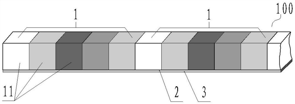
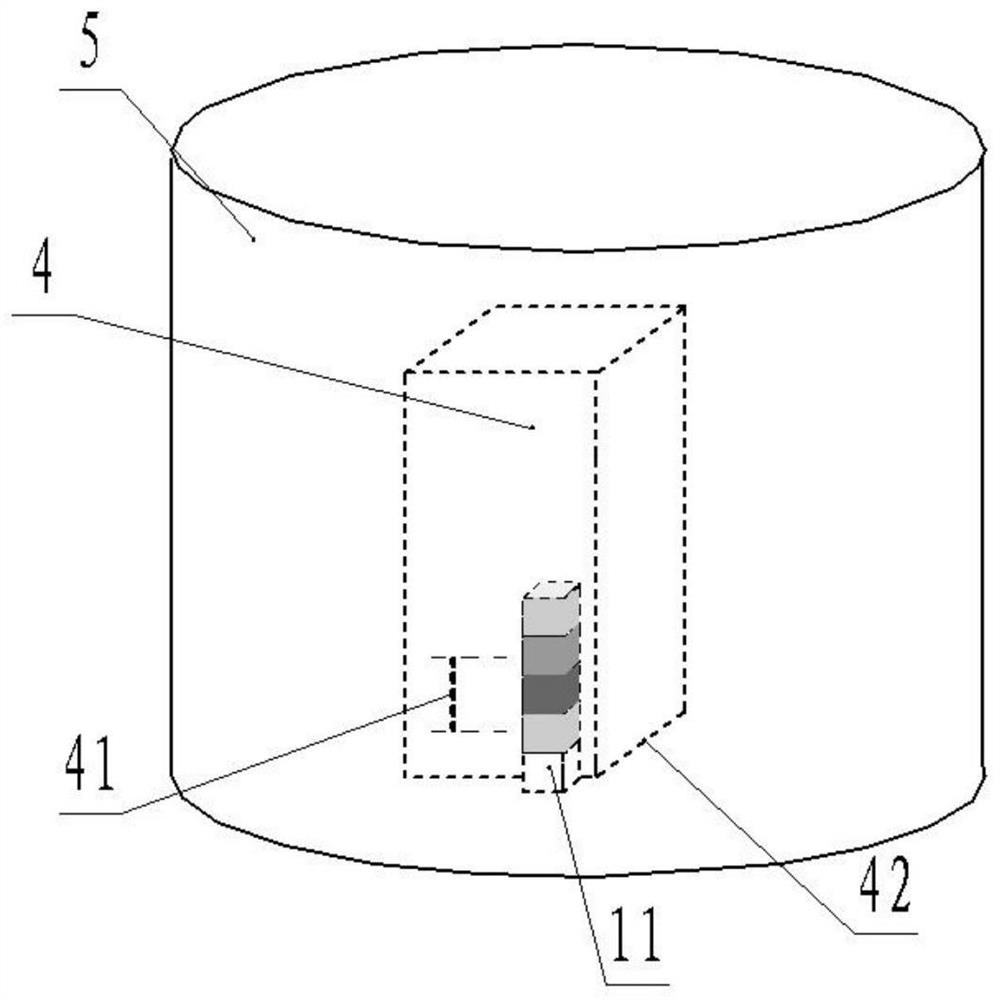
[0030] Such as figure 1...


PUM


Abstract

A mark card for marking the position of the metallographic inlay sample is of a cuboid structure composed of a plurality of color block groups, and each color block group is internally provided with a plurality of color blocks with different colors. The use method of the marking card comprises the following steps: S1, according to the length of a to-be-detected sample and the length of a defect on the to-be-detected sample, cutting out the marking card with a proper length, and adhering the marking card to one side of the defect position on the to-be-detected sample, so that the length direction of the marking card is along the length direction of the defect, and the lower end surface of the marking card is parallel to the grinding and polishing surface of the to-be-detected sample; S2, recording colors of color blocks corresponding to the positions of the lower end and the upper end of the defect; S3, embedding the to-be-detected sample adhered with the marking card to obtain an embedded sample; S4, grinding and polishing the inlaid sample, and when the inlaid sample is ground and polished to the color of a color block corresponding to the lower end of the defect displayed by the marking card, grinding and polishing the defect close to the defect, wherein if the defect is polished to the color of the color block corresponding to the upper end of the defect displayed by the marking card, the defect is about to be polished to the tail end.

Description

technical field [0001] The invention relates to the technical field of physical and chemical performance detection, in particular to a marking card for marking the position of a metallographic inlay sample and a use method thereof. Background technique [0002] In the testing of physical and chemical properties, due to the irregular shape of some samples, in order to fix the samples or standardize the shape of the samples, the metallographic samples should be inlaid before grinding and polishing. [0003] Metallographic sample mounting includes hot mounting and cold mounting. The thermal mounting process is generally a process in which the sample is first placed in the mounting cylinder, and then the mounting powder is poured into the mounting cylinder to bury the sample, and then pressurized and heated to make the resin vitrified and the sample integrated. Commonly used thermal mounting material powders include phenolic resin, acrylic resin, epoxy resin, etc. Generally, th...

Claims


Application Information

Patent Timeline
Patent Type & Authority Applications(China)
IPC IPC(8): G01N1/28G01N1/32
CPCG01N1/286G01N1/32
Inventor 汤浩刘依依陈娇雷旭
Owner CHINA HANGFA GUIZHOU LIYANG AVIATION POWER CO LTD
Learn More