Yarn guide device for fiber laying

A yarn guide device and fiber laying technology, which is applied in the processing field of fiber laying, can solve the problems of increasing the volume of winding equipment, limiting the freedom of robot movement, and high equipment costs, so as to save space, reduce costs, and simplify laying The effect of system structure

Pending Publication Date: 2022-08-02
HARBIN INST OF TECH
View PDF0 Cites 1 Cited by
  • Summary
  • Abstract
  • Description
  • Claims
  • Application Information

AI Technical Summary

Problems solved by technology

[0003] In order to solve the problem that the traditional floor-type creel guide mechanism limits the freedom of movement of the robot, it is necessary to use a multi-degr

Method used


Image

  • Yarn guide device for fiber laying
  • Yarn guide device for fiber laying
  • Yarn guide device for fiber laying

Examples


specific Embodiment approach 1

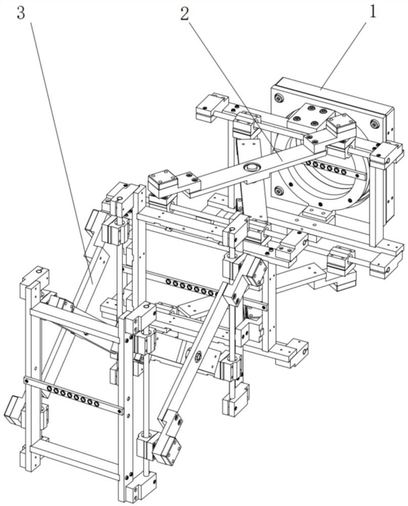
[0014] Embodiment 1: Combining Figure 1-Figure 5 This embodiment is described. A yarn guide device for fiber laying described in this embodiment includes a rotating mechanism 1, a pitching mechanism 2 and a swinging mechanism 3. The fixed end of the rotating mechanism 1 is fixedly connected with the yarn guide frame and rotates The rotating end of the mechanism 1 is connected with the fixed end of the pitching mechanism 2, the moving end of the pitching mechanism 2 is connected with the fixed end of the swinging mechanism 3, the moving end of the swinging mechanism 3 is connected with the yarn guide, and the fiber tow is connected by the rotating mechanism 1 in turn. It is provided through the pitch mechanism 2 and the swing mechanism 3.

specific Embodiment approach 2

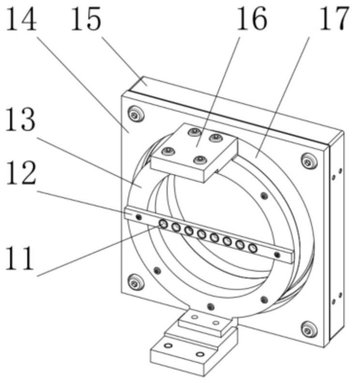
[0015] Specific implementation mode 2: Combining Figure 1-Figure 2 Illustrating this embodiment, a yarn guide device for fiber laying described in this embodiment, the rotating mechanism 1 includes a first ceramic ring support 12, a bearing connecting ring 13, a bearing seat cover 14, a bearing seat 15, a cross Roller bearing 17, two connecting blocks 16 and multiple first yarn guide ceramic rings 11; multiple first yarn guide ceramic rings 11 are mounted on the first ceramic ring support 12, and the first ceramic ring support 12 is fixedly mounted on the bearing On the connecting ring 13, two connecting blocks 16 are symmetrically arranged and fixedly installed on the bearing connecting ring 13, the bearing connecting ring 13 is fixedly installed on the inner ring of the crossed roller bearing 17, and the outer ring of the crossed roller bearing 17 is installed on the bearing. Inside the seat 15 , the bearing seat cover plate 14 is mounted on the bearing seat 15 , and the fi...

specific Embodiment approach 3

[0016] Specific implementation three: combination Figure 1-Figure 2 Describing this embodiment, a yarn guide device for fiber laying described in this embodiment, a plurality of first yarn guide ceramic rings 11 are arranged in a straight line and installed on the first ceramic ring support 12 . A plurality of first yarn-guiding ceramic rings 11 are installed on the first ceramic ring support 12 at a certain interval to control the fiber spacing to avoid entanglement between fibers and excessive friction to damage the fibers. Others are the same as in the second embodiment.


PUM


Abstract

The invention relates to a yarn guide structure of fibers, in particular to a yarn guide device for fiber laying, and aims to solve the problems that a traditional floor type creel yarn guide mechanism limits the degree of freedom of motion of a robot, needs to use a multi-degree-of-freedom mold rotary table to increase the size of winding equipment and is high in equipment cost. The fixed end of the rotating mechanism is fixedly connected with the yarn guide frame, the rotating end of the rotating mechanism is connected with the fixed end of the pitching mechanism, the movable end of the pitching mechanism is connected with the fixed end of the swing mechanism, the movable end of the swing mechanism is connected with the yarn guide frame, and a fiber tow sequentially penetrates through the pitching mechanism and the swing mechanism from the rotating mechanism. The invention belongs to the processing field of fiber laying.

Description

technical field [0001] The present invention relates to a yarn guiding structure for fibers, in particular to a yarn guiding device for laying fibers. It belongs to the processing field of fiber placement. Background technique [0002] Carbon fiber composite components formed by automatic fiber placement technology have a wide range of applications in the aerospace field. Fiber placement technology is a molding method of resin-based fiber-reinforced composite materials, which lays fiber bundles on a mold according to a certain trajectory, and then solidifies and shapes to obtain the final product. With the development of robotics technology, 6-DOF serial robots have been widely used in the field of fiber placement. When it is on the wrist, the yarn storage capacity of the laying system will be limited by the rated load of the robot, and at the same time, the creel will occupy the space of the laying head, which will bring difficulties to the design of the laying head. The...

Claims


Application Information

Patent Timeline
IPC IPC(8): B29C70/38B29C70/32
CPCB29C70/384B29C70/32
Inventor 金鸿宇李品华韩振宇孙守政富宏亚
Owner HARBIN INST OF TECH
Why Eureka
Try Eureka