Hot-pressing device for quickly forming multilayer building template

A technology of construction formwork and hot pressing device, which is applied in the direction of lamination device, lamination, lamination auxiliary operation, etc. It can solve the problems of inconvenient formwork pick and place, inability to limit formwork, formwork displacement, etc., to achieve convenient operation, Avoid the effect of template displacement and avoid impact

Pending Publication Date: 2022-08-02
杭州忆晨网络科技有限公司
View PDF1 Cites 0 Cited by
  • Summary
  • Abstract
  • Description
  • Claims
  • Application Information

AI Technical Summary

Problems solved by technology

[0005] In order to overcome the disadvantages of the above-mentioned prior art that it is inconvenient to take and place the template, and the template cannot be limited, it is easy to displace the template during the hot pressing operation, resulting in a bad hot pressing effect. The technica

Method used


Image

  • Hot-pressing device for quickly forming multilayer building template
  • Hot-pressing device for quickly forming multilayer building template
  • Hot-pressing device for quickly forming multilayer building template

Examples


Example Embodiment

[0030] Example 1

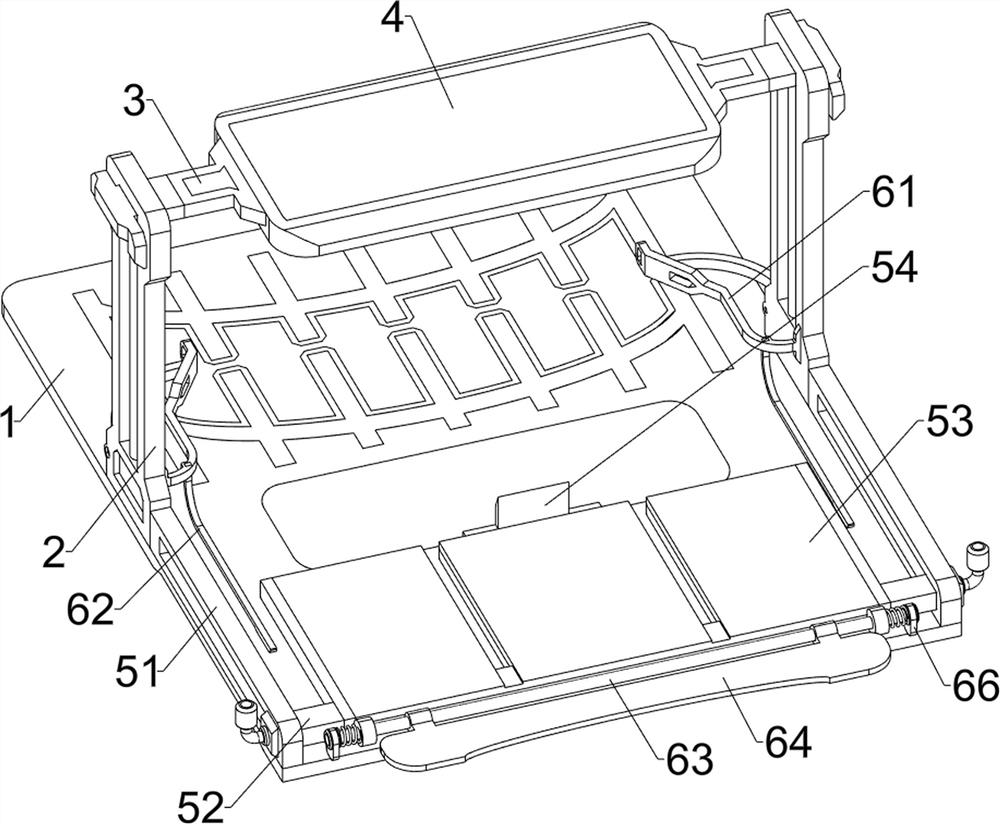
[0031] A rapid prototyping multi-layer building formwork hot pressing device, such as Figure 1-3 As shown, it includes a fixed plate 1, an electric slide rail 2, a connection block 3, a hot pressing plate 4, a transport mechanism 5 and a limit mechanism 6. The upper side of the middle of the fixed plate 1 is symmetrically installed with an electric sliding plate connected by screws. Rail 2, the upper part of the electric sliding rail 2 is slidably provided with a connecting block 3, a hot pressing plate 4 is welded between the two connecting blocks 3, and a transport mechanism 5 is arranged on the fixed plate 1, and the transport mechanism 5 and the electric sliding rail 2 are arranged between A limiting mechanism 6 is provided.

[0032] like figure 2 As shown, the transport mechanism 5 includes a guide rail 51, a sliding block 52, a placing board 53 and a clamping board 54, and a guide rail 51 is bolted symmetrically on the upper side of the front part ...

Example Embodiment

[0035] Example 2

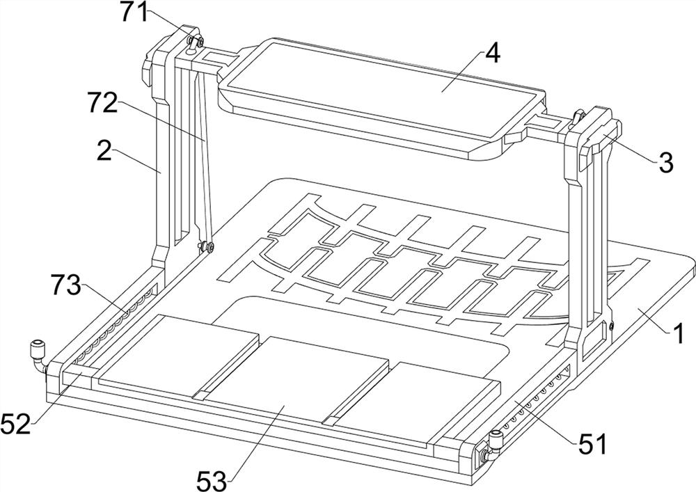
[0036] On the basis of Example 1, as figure 1 , Figure 4 and Figure 5 As shown, it also includes a power mechanism 7. The power mechanism 7 includes a pulley 71, a pulling rope 72 and a first spring 73. Two pulleys 71 are rotatably provided on the opposite sides of the two electric sliding rails 2. The pulley 71 is arranged up and down, a pull rope 72 is connected between the slider 52 and the hot pressing plate 4 on the same side, the pull rope 72 goes around the pulley 71, and a first spring 73 is connected between the slider 52 and the guide rail 51 on the same side .

[0037] When the operator places the template on the placing plate 53, the operator starts the electric slide rail 2, so that the electric slide rail 2 drives the hot pressing plate 4 to move downward through the connecting block 3, and the connecting block 3 moves downward through the pulling rope 72. Pull the slider 52 to move backward, the first spring 73 compresses, the slider 52 wi...

Example Embodiment

[0038] Example 3

[0039] On the basis of Example 2, as figure 1 and Image 6 As shown, it also includes a scraping mechanism 8, the scraping mechanism 8 includes a first connecting rod 81, a second spring 82 and a scraper 83, a first connecting rod 81 is bolted on the upper side of the guide rail 51, and two first connecting rods A scraper 83 is slidably sleeved between the upper part of the rod 81 . The upper side of the scraper 83 is symmetrically provided with a rubber handrail, which can facilitate the movement of the scraper 83 . A second spring 82 is connected between the scraper 83 and the first connecting rod 81 .

[0040] When placing the multi-layer template to be hot-pressed on the placement plate 53, the operator drives the scraper 83 to move downward, the second spring 82 is compressed, and the scraper 83 moves downward to scrape off the adhesive overflowing from the outside of the template, and then the operator When the scraper 83 is released, the second spri...


PUM


Abstract

The invention relates to a hot-pressing device, in particular to a hot-pressing device for rapidly forming a multi-layer building template. According to the hot-pressing device for rapidly forming the multi-layer building template, taking and placing operation of the template is facilitated, the template can be limited, template displacement is avoided, and the hot-pressing effect is guaranteed. The hot pressing device for rapidly forming the multi-layer building formwork comprises a fixing plate, electric sliding rails, connecting blocks, a hot pressing plate and the like, the electric sliding rails are installed on the upper side of the middle of the fixing plate in a bilateral symmetry mode, the connecting blocks are arranged on the upper portions of the electric sliding rails in a sliding mode, and the hot pressing plate used for pressing the formwork is connected between the two connecting blocks. The placing plate drives the template to move, taking and placing of the template are facilitated, the limiting rod and the limiting plate can limit the positions of the placing plate and the template correspondingly, the template is located under the hot pressing plate, displacement of the template can be avoided, and a good hot pressing effect can be achieved.

Description

technical field [0001] The invention relates to a hot pressing device, in particular to a hot pressing device for a rapid prototyping multi-layer building formwork. Background technique [0002] In construction engineering, building formwork is a temporary support structure used when pouring concrete. It is mainly composed of three panels with different functions bonded together. This type of formwork has strong support and is not good for sticking to cement. Most building formwork is made by hot pressing device using hot pressing technology. When the hot pressing device in the prior art performs the hot pressing operation of the template, it is difficult to accurately place the template to be hot pressed on the At the position corresponding to the hot pressing device, and the template cannot be limited, it is easy to displace the template during the hot pressing operation of the hot pressing device, which will cause the template to be stepped and affect the use of the templ...

Claims


Application Information

Patent Timeline
IPC IPC(8): B32B37/10B32B37/06B32B37/08B32B37/12B32B38/16B32B38/18
CPCB32B37/10B32B37/06B32B37/1284B32B38/162B32B37/08B32B38/1833
Inventor 朱绍雄
Owner 杭州忆晨网络科技有限公司
Why Eureka
Try Eureka