
Power back-twisting pay-off machine

A technology of power and pay-off reel, which is applied in the direction of thin material processing, delivery of filamentous materials, transportation and packaging, etc., which can solve the problems of uneven force on the pay-off reel, lower production efficiency, high operating noise, etc., and achieve wear and tear Small size, improved production efficiency, and smooth operation

Pending Publication Date: 2022-08-02
钲威电工科技(江苏)有限公司
View PDF0 Cites 0 Cited by
  • Summary
  • Abstract
  • Description
  • Claims
  • Application Information

AI Technical Summary

Problems solved by technology

[0003] However, the pay-off reel of the existing untwisting machine is generally a shaft-through-shaft structure. The pay-off reel and the turntable are supported by a unilateral bearing seat, and the other side has no support and is in a suspended state. Therefore, the pay-off When the reel rotates and pays off, it is only subjected to the torque of one end of the pay-off reel, so that the force on both ends of the pay-off reel is uneven, and large vibrations will be generated when rotating at high speed, resulting in louder running noise and uneven operation. Stable, thereby reducing production efficiency

Method used


Image

  • Power back-twisting pay-off machine
  • Power back-twisting pay-off machine
  • Power back-twisting pay-off machine

Examples


Embodiment Construction

[0022] In order to describe in detail the technical content, structural features, and achieved effects of the present invention, detailed descriptions are given below with reference to the embodiments and the accompanying drawings.

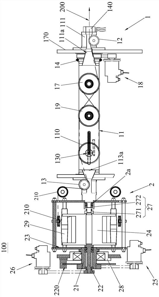
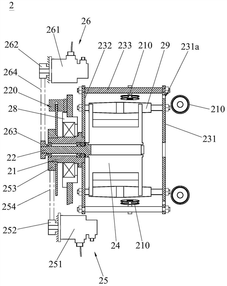
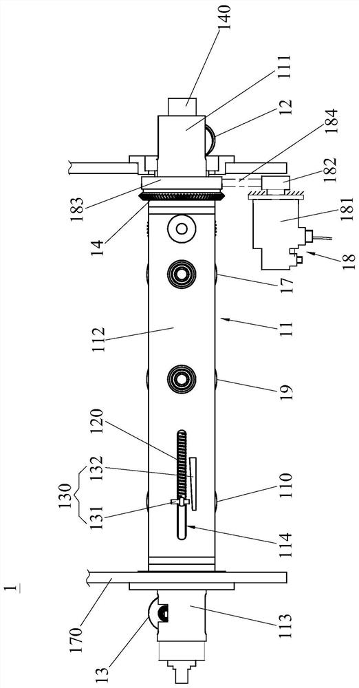
[0023] like Figure 1 to Figure 2 As shown, the power untwisting pay-off machine 100 of the present invention is suitable for untwisting and paying off the core wire 200, and it includes a pay-off tension mechanism 1 and a pay-off mechanism 2; the pay-off mechanism 2 includes a main shaft 21, a pay-off shaft 22. Turntable 23, pay-off reel 24, turntable drive mechanism 25 and reel drive mechanism 26, the main shaft 21 is coaxially and rotatably sleeved outside the pay-off reel 22; The center is detachably connected to one end of the pay-off shaft 22, and the center of the other side of the pay-off reel 24 is coaxial and rotatable with the rotation center axis of the pay-off tension mechanism 1 through a bearing 2a. The center of one side of the tu...


PUM


Abstract

The invention discloses a power back-twist pay-off machine which comprises a pay-off mechanism and a pay-off tension mechanism. The pay-off mechanism comprises a main shaft, a pay-off shaft, a rotating disc, a pay-off disc, a rotating disc driving mechanism and a wire disc driving mechanism. The main shaft is coaxially and rotatably arranged outside the pay-off shaft in a sleeving mode. The center of one side of the pay-off reel is connected to one end of the pay-off shaft, and the center of the other side of the pay-off reel is coaxially and rotatably connected with a rotating center shaft of the pay-off tension mechanism; the center of one side of the rotating disc is fixedly connected to one end of the main shaft, and the center of the other side of the rotating disc is coaxially and fixedly connected with the rotating center shaft; the rotating disc driving mechanism drives the main shaft to rotate; and the wire coil driving mechanism drives the pay-off shaft to rotate. According to the power back-twisting pay-off machine, the two shafts are supported on the two sides of the pay-off disc and the rotary disc, so that the pay-off disc and the rotary disc operate more stably, vibration is small, noise is low, and the production efficiency is effectively improved.

Description

technical field [0001] The invention relates to a cable production equipment, in particular to a power untwisting and pay-off machine. Background technique [0002] The traditional cable stranding process is a production process in which multiple strands of thin wires are twisted into a single cable. , the multi-strand thin wires are combined and rotated along the central axis of the incoming wire of the stranding machine, thereby twisting the multi-strand thin wires into a cable. In traditional stranding, one side of the strand is rotated, and the pay-off and untwisting machine on the pay-off side outputs the wire through back-twisting. This process is the back-twisting and pay-off twisting process. Using the untwisting and pay-off process, the twisted cable has no internal stress inside, the cable has a soft appearance, and has good electrical performance. It is especially suitable for robot drag chain cables, signal cables, aviation cables, etc. [0003] However, the pa...

Claims


Application Information

Patent Timeline
IPC IPC(8): B65H49/34B65H59/38B65H49/20B65H63/00B65H59/10B65H57/14
CPCB65H49/34B65H59/38B65H49/20B65H63/00B65H59/10B65H57/14B65H2701/39
Inventor 夏自安李爱琴
Owner 钲威电工科技(江苏)有限公司
Learn More