
Diaphragm winding roller

A technology for winding rollers and diaphragms, which is applied in the direction of climate sustainability, final product manufacturing, sustainable manufacturing/processing, etc. It can solve problems such as the inability to flatten the winding diaphragm, and achieve the effect of avoiding deformation and uniform deformation space

Inactive Publication Date: 2022-08-02
苏州益永精工制造有限公司
View PDF1 Cites 1 Cited by
  • Summary
  • Abstract
  • Description
  • Claims
  • Application Information

AI Technical Summary

Problems solved by technology

[0005] Based on this, the purpose of the present invention is to provide a diaphragm winding roller to solve the technical problem that the existing diaphragm winding roller cannot roll the diaphragm smoothly.

Method used


Image

  • Diaphragm winding roller
  • Diaphragm winding roller
  • Diaphragm winding roller

Examples


Embodiment Construction

[0037] The technical solutions in the embodiments of the present invention will be clearly and completely described below with reference to the accompanying drawings in the embodiments of the present invention. The embodiments described below with reference to the accompanying drawings are exemplary, only used to explain the present invention, and should not be construed as a limitation of the present invention.

[0038] The embodiments of the present invention will be described below based on the overall structure of the present invention.

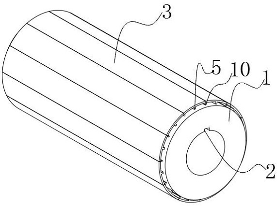
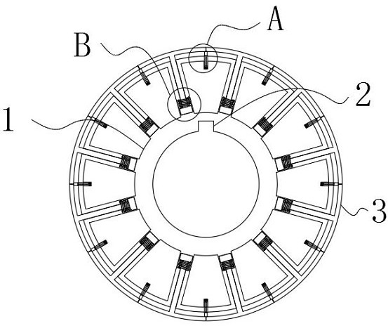
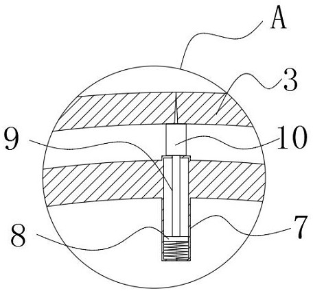
[0039] A diaphragm take-up roll such as Figure 1-7 As shown, the inner wall of the cylinder body 1 is provided with a keyway 2, and the cylinder body 1 is connected with the drive shaft through the keyway 2, and then the drive shaft drives the cylinder body 1 to rotate. 3. A continuous circle is formed on the radial plane of the cylinder body 1, and the cylinder body 1 is slidably provided with a supplementary strip 10 at the gap before...


PUM


Abstract

The invention discloses a diaphragm winding roller, and relates to the field of diaphragm winding rollers, the diaphragm winding roller comprises a roller body, a plurality of groups of sliding plates are slidably connected in the roller body, the plurality of groups of sliding plates form a continuous circle on the radial plane of the roller body, and the roller body is slidably provided with position covering strips at gaps in front of the two groups of sliding plates; after the cylinder body rotates, the multiple sets of position covering strips and the sliding plate form a continuous circle on the radial plane of the cylinder body. The sliding plates under the action of the rotating centrifugal force of the roller are arranged in the roller, the position covering sliding columns are arranged in the gaps between every two adjacent sets of sliding plates, the position covering strips are arranged at the top ends of the position covering sliding columns, and when the roller starts to rotate to wind the diaphragm, the multiple sets of sliding plates and the position covering strips extend outwards under the centrifugal force to form the large-diameter roller to wind the diaphragm; due to the fact that the roller surface of the large-diameter roller is filled with the multiple sets of position covering strips, the roller surface of the large-diameter roller is an uninterrupted arc surface, a large gap does not exist in the gap between every two adjacent sets of sliding plates, and the situation that a diaphragm at the gap deforms is avoided.

Description

technical field [0001] The invention relates to the field of diaphragm winding rollers, in particular to a diaphragm winding roller. Background technique [0002] The separator plays an important role in the application of lithium batteries, and the consistency of the thickness of the separator has become a key factor restricting the improvement of the quality of the separator. During the post-processing of the separator, the temperature, stress, and gas inside the separator will be slowly released over time. , During the release process, the diaphragm will shrink to a certain extent, but the diameter of the winding roller where the diaphragm is located remains unchanged, and the winding tension of the diaphragm cannot be effectively released. The unevenness and the deepening of the thin and thick bands affect the thickness consistency of the diaphragm. [0003] The related Chinese patent publication number CN106081747B discloses a diaphragm winding drum, which includes a c...

Claims


Application Information

Patent Timeline
Patent Type & Authority Applications(China)
IPC IPC(8): B65H75/10B65H75/24B65H75/18
CPCB65H75/10B65H75/242B65H75/18B65H2701/1133Y02P70/50
Inventor 赵锋刘述见
Owner 苏州益永精工制造有限公司
Learn More