
Deep-well pump and impeller transmission structure

A transmission structure and impeller technology, applied in pumps, pump components, pump devices, etc., can solve problems affecting the working stability of deep well pumps, impeller shaft friction cutting, and rotation center offset, etc., to ensure the safety of pump water and reduce Radial swing, reducing radial wear effect

Pending Publication Date: 2022-08-02
ZHEJIANG KAIBORUI AUTOPARTS CO LTD
View PDF0 Cites 0 Cited by
  • Summary
  • Abstract
  • Description
  • Claims
  • Application Information

AI Technical Summary

Problems solved by technology

However, after the impeller shaft has been working for a long time, its rotation center will shift, resulting in contact wear between the impeller shaft and the O-shaped friction plate. In severe cases, there will be a problem of friction and cutting between the O-shaped friction plate and the impeller shaft, which will affect the working stability of the deep well pump.

Method used


Image

  • Deep-well pump and impeller transmission structure
  • Deep-well pump and impeller transmission structure

Examples


Embodiment Construction

[0020] The invention discloses an impeller transmission structure, which improves the stability of the deep well pump in the working process; the invention also provides a deep well pump.

[0021] The technical solutions in the embodiments of the present invention will be clearly and completely described below with reference to the accompanying drawings in the embodiments of the present invention. Obviously, the described embodiments are only a part of the embodiments of the present invention, not all of the embodiments. Based on the embodiments of the present invention, all other embodiments obtained by those of ordinary skill in the art without creative work fall within the protection scope of the present invention.

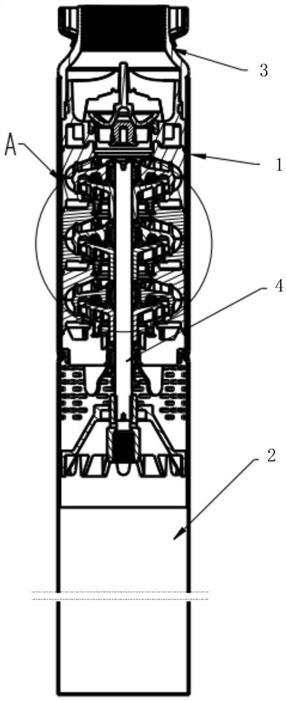
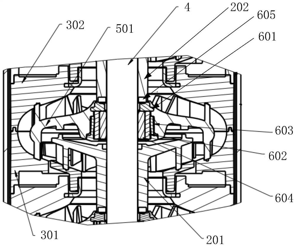
[0022] like figure 1 and figure 2 shown, figure 1 A schematic structural diagram of the deep well pump provided in this embodiment; figure 2 for figure 1 Partial enlarged view at A.

[0023] The deep well pump consists of a pump body 1 and a motor 2. The...


PUM


Abstract

According to the impeller transmission structure, the anti-wear structure is arranged in the guide vane, meanwhile, the rear-end impeller is supported, radial swing of the pump shaft is supported, the anti-wear structure is arranged in the mode that the first supporting part is close to the rear-end impeller, and in the water pumping process, the impeller shaft end of the rear-end impeller abuts against the first supporting part; and the supporting stability of the rear-end impeller in the water pumping process is ensured. The second supporting part supports the pump shaft in the radial direction, radial swing of the pump shaft is reduced, radial abrasion of the pump shaft is reduced, the rear-end impeller and the pump shaft are independently supported through the first supporting part and the second supporting part, the supporting stability of the rear-end impeller and the pump shaft is guaranteed, and meanwhile the water pumping safety of the deep-well pump working for a long time is guaranteed. The invention further provides a deep-well pump.

Description

technical field [0001] The invention relates to the technical field of deep well pumps, in particular to a deep well pump and an impeller transmission structure. Background technique [0002] In the existing guide seat structure of the deep well pump, the impeller is used to pump water between adjacent guide seats, the impeller is driven to rotate synchronously by the impeller shaft, and the guide body is arranged in the guide seat to cooperate with the impeller pump water. [0003] When the guide body and the impeller are arranged, the guide body is fixed in the guide seat, the pump water end of the impeller is matched with the guide body to pump water, the shaft end of the impeller extends into the shaft hole of the upper guide body, and the shaft of the guide body The holes are usually arranged with O-type friction plates to support the shaft end of the impeller. However, after the impeller shaft works for a long time, its rotation center will be offset, resulting in con...

Claims


Application Information

Patent Timeline
Patent Type & Authority Applications(China)
IPC IPC(8): F04D29/046F04D29/04F04D29/02F04D29/66F04D29/54F04D13/10
CPCF04D29/046F04D29/04F04D29/026F04D29/669F04D29/548F04D13/10
Inventor 薛红俊程福才柯新忠范丽华
Owner ZHEJIANG KAIBORUI AUTOPARTS CO LTD
Learn More