
Movement assembly, laser radar and light path adjusting method

An optical path adjustment and assembly technology, used in instruments, measuring devices, and re-radiation, etc., can solve the problems of low dimming efficiency and complicated optical path adjustment, and achieve the effect of simplifying the adjustment process and improving the dimming efficiency.

Pending Publication Date: 2022-08-02
TANWAY TECH (BEIJING) CO LTD
View PDF0 Cites 1 Cited by
  • Summary
  • Abstract
  • Description
  • Claims
  • Application Information

AI Technical Summary

Problems solved by technology

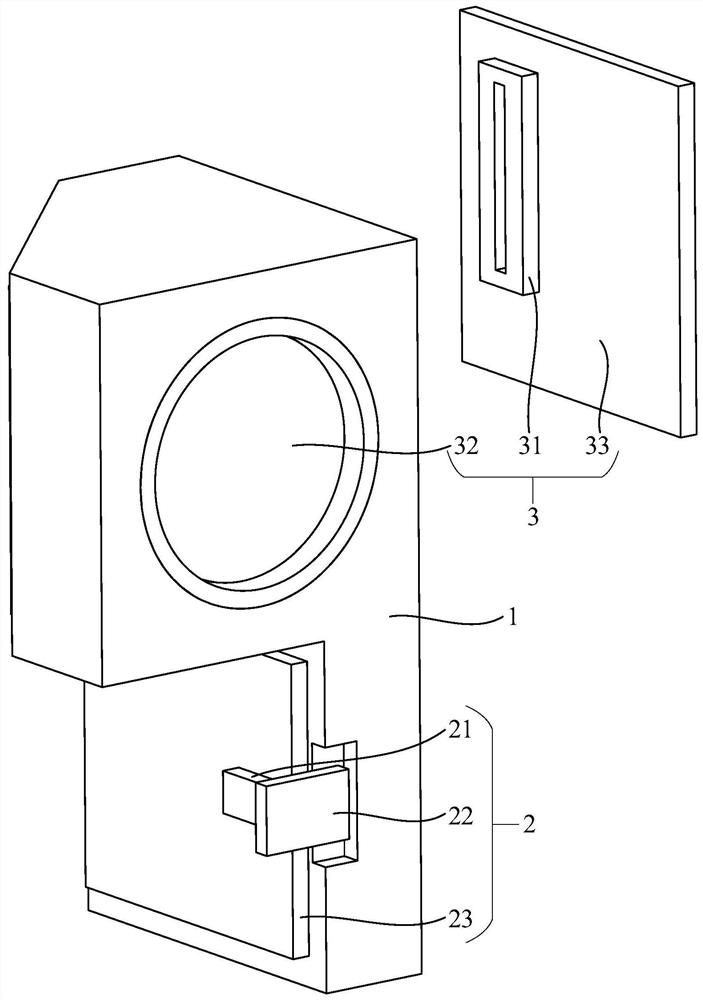
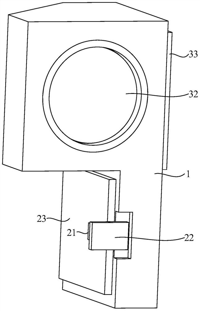
[0005] The present application provides a movement assembly, a laser radar, and an optical path adjustment method, which can overcome the problems of complicated optical path adjustment and low dimming efficiency existing in related technologies

Method used


Image

  • Movement assembly, laser radar and light path adjusting method
  • Movement assembly, laser radar and light path adjusting method
  • Movement assembly, laser radar and light path adjusting method

Examples


Embodiment Construction

[0043] In order to make the objectives, technical solutions and advantages of the present disclosure clearer, the embodiments of the present disclosure will be further described in detail below with reference to the accompanying drawings.

[0044] An embodiment of the present application provides a movement assembly, which is applied to a laser radar, a laser radar, which is a radar system that emits a laser beam to detect characteristic quantities such as the position and velocity of a target. Its working principle is to transmit a detection signal (which can be called a detection beam) to the target, and then compare the received signal reflected from the target (which can be called an echo beam) with the detection signal, and after proper processing, it can be obtained. Information about the target, such as target distance, azimuth, altitude, speed, attitude, and even shape and other parameters, so as to detect, track and identify targets such as aircraft and missiles.

[0...


PUM


Abstract

The invention relates to a movement assembly, a laser radar and a light path adjusting method, and belongs to the technical field of laser radars. The movement assembly comprises an assembly seat, a laser emitting assembly and a laser receiving assembly, and the laser receiving assembly comprises a laser receiver and a receiving lens; the laser emitting assembly, the laser receiver and the receiving lens are all installed on the assembly base, and the laser receiver is located on an emergent light path of the receiving lens. Before the movement assembly completes light path adjustment, the laser emitting assembly is adjustable relative to the assembly base, and the receiving lens can stretch out and draw back in the light beam incidence direction relative to the assembly base. According to the invention, the adjustment process of the light path can be simplified, and the dimming efficiency is improved.

Description

technical field [0001] This application relates to the technical field of lidar, in particular to a movement assembly, lidar and optical path adjustment method. Background technique [0002] Laser Radar is a radar system that emits laser beams to detect the position and velocity of the target and other characteristic quantities. It is an active detection technology that can accurately and quickly obtain the three-dimensional spatial information of the target. [0003] In order to achieve accurate and clear three-dimensional imaging of the lidar, it is necessary to precisely align the optical path of the lidar, such as the accurate alignment of the echo beam reflected from the target and the laser receiver. [0004] However, at present, the adjustment of the optical path is more complicated, and the dimming efficiency is low. SUMMARY OF THE INVENTION [0005] The present application provides a movement assembly, a laser radar and an optical path adjustment method, which ca...

Claims


Application Information

Patent Timeline
Patent Type & Authority Applications(China)
IPC IPC(8): G01S17/06G01S17/58G01S17/89G01S7/481
CPCG01S17/06G01S17/58G01S17/89G01S7/4814G01S7/4816
Inventor 陈源张正杰时菲菲沈罗丰李洪鹏
Owner TANWAY TECH (BEIJING) CO LTD
Learn More