
Driving area detection method, device and equipment

A driving area and detection method technology, applied in the field of drivable area detection, can solve the problems of unstable road edge occlusion recognition, poor robustness of undulating roads, and insufficient detection accuracy.

Active Publication Date: 2022-08-02
HOZON NEW ENERGY AUTOMOBILE CO LTD
View PDF6 Cites 1 Cited by
  • Summary
  • Abstract
  • Description
  • Claims
  • Application Information

AI Technical Summary

Problems solved by technology

[0004] The embodiment of the present application provides a drivable area detection method, device and equipment, which are used to solve the problems existing in the prior art such as unstable roadside occlusion recognition, poor robustness of undulating roads, and insufficient detection accuracy.

Method used


Image

  • Driving area detection method, device and equipment
  • Driving area detection method, device and equipment
  • Driving area detection method, device and equipment

Examples


Embodiment Construction

[0064] In order to make the objectives, technical solutions and advantages of the present invention clearer, the present invention will be further described in detail below with reference to the accompanying drawings.

[0065] The application scenarios described in the embodiments of the present application are for the purpose of illustrating the technical solutions of the embodiments of the present application more clearly, and do not constitute a limitation on the technical solutions provided by the embodiments of the present application. It appears that the technical solutions provided by the embodiments of the present application are also applicable to similar technical problems. Wherein, in the description of the present application, unless otherwise specified, the meaning of "plurality" is two or more.

[0066] It should be noted that the terms "first", "second", etc. in the description and claims of the present application and the above drawings are used to distinguish ...


PUM


Abstract

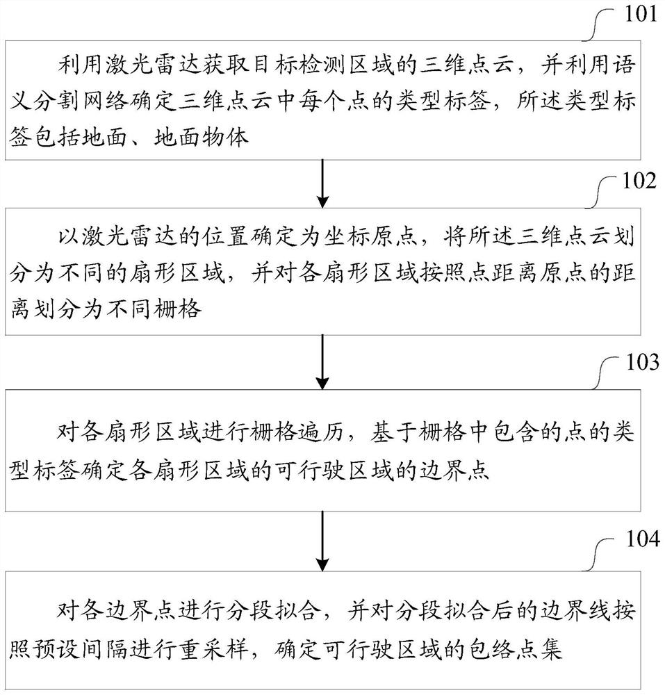
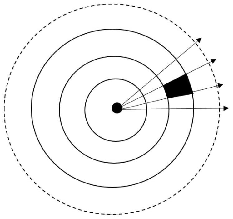
The invention provides a drivable area detection method, device and equipment, and the method comprises the steps: obtaining a three-dimensional point cloud of a target detection area through a laser radar, determining the type label of each point in the three-dimensional point cloud through a semantic segmentation network, and enabling the type labels to comprise the ground and a ground object; determining the position of the laser radar as a coordinate origin, dividing the three-dimensional point cloud into different fan-shaped regions, and dividing each fan-shaped region into different grids according to the distance from the point to the origin; performing grid traversal on each fan-shaped region, and determining boundary points of a drivable region of each fan-shaped region based on type labels of points contained in grids; performing segmentation fitting on each boundary point, performing resampling on boundary lines after segmentation fitting according to a preset interval, and determining an envelope point set of a drivable area; according to the method, the problems of unstable road edge shielding identification, poor rugged road robustness, insufficient detection precision and the like in the prior art are effectively solved.

Description

technical field [0001] The present application relates to the technical field of automatic driving perception, and in particular, to a method, device and device for detecting a drivable area. Background technique [0002] Autonomous driving technology is a complex engineering system, which requires the cooperation of various modules to ensure the safety of driving in an all-round way. Among them, the free space detection technology is one of the key technologies of the autonomous driving system, which can provide a basis for back-end modules such as path planning and behavior decision-making. Camera images and LiDAR point clouds are currently the main data input sources used to detect drivable areas. In the method of extracting drivable areas based on images, the color or texture features used are easily disturbed by light and weather, and the lack of three-dimensional information also limits the adaptability of such algorithms in different scenarios. Lidar can provide ric...

Claims


Application Information

Patent Timeline
Patent Type & Authority Applications(China)
IPC IPC(8): G06V20/58G06V10/25G06V10/26
CPCG06V20/58G06V10/26G06V10/25G06V2201/07Y02A90/10
Inventor 潘奇张灿王文爽赵天坤
Owner HOZON NEW ENERGY AUTOMOBILE CO LTD
Learn More