Electric power overhaul device for electric power overhaul
A technology for electric power maintenance and external surface, applied in the direction of electromechanical devices, cleaning methods using tools, electrical components, etc., can solve problems such as troublesome operation, affect the accuracy of maintenance, prolong the cycle of maintenance, etc., to achieve convenient operation, save time and physical strength , The effect of improving maintenance efficiency
- Summary
- Abstract
- Description
- Claims
- Application Information
AI Technical Summary
Problems solved by technology
Method used
Image
Examples
Embodiment 1
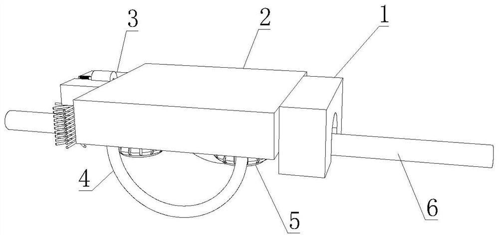
[0035] like Figure 1-5 As shown, the present invention provides a power maintenance device for power maintenance, including a power maintenance device body 1, a sunscreen mechanism 2 is fixedly connected to the left side of the power maintenance device body 1, and the sunscreen mechanism 2 includes a hollow microbead plate 26. The hollow microbead plate 26 is provided with a circular hole 28. The lower side of the sunscreen mechanism 2 is fixedly connected with a ring-shaped handle 4, and the interior of the sunscreen mechanism 2 is movably connected with a movable clamping mechanism 5. The movable clamping mechanism 5. Including a clamping wheel 54, the outer side of the clamping wheel 54 is provided with a curved groove 52, the outer side of the clamping wheel 54 is provided with a sheet groove 53, the inner wall of the curved groove 52 is overlapped with a cable 6, and the left side of the sunscreen mechanism 2 A cleaning mechanism 3 is fixedly connected, and the cleaning ...
Embodiment 2
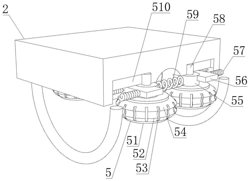
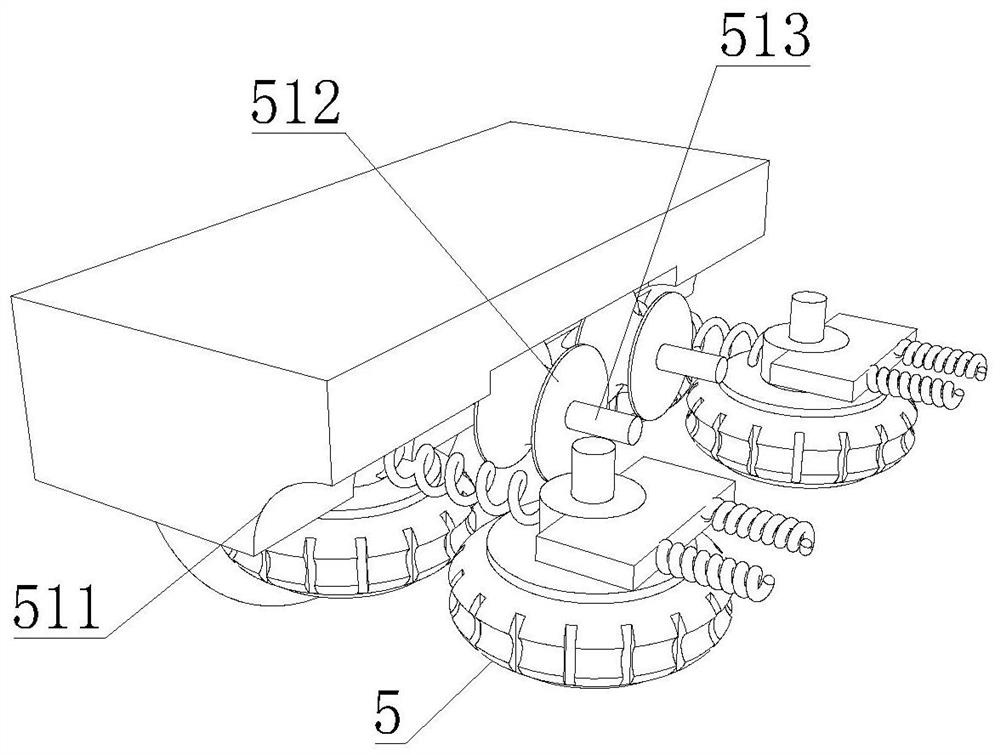
[0038] like Figure 1-5As shown, on the basis of Embodiment 1, the present invention provides a technical solution: preferably, a wheel shaft 51 is fixedly connected to the inside of the clamping wheel 54, and a central shaft 58 is rotatably connected to the center of the shaft center of the wheel shaft 51. The upper side is lapped with the second bearing 55, the inner wall of the second bearing 55 is fixedly installed with the outer surface of the central shaft 58, one side of the second bearing 55 is fixedly connected with a moving block 56, and the other side of the second bearing 55 is fixedly connected with a connecting spring 59 , the other side of the moving block 56 is fixedly connected with a built-in spring 57, the outer surface of the central shaft 58 is overlapped with a special-shaped groove 510, and the inner wall of the special-shaped groove 510 is overlapped with the outer surface of the bearing two 55 and the outer surface of the moving block 56, The other end...
Embodiment 3
[0041] like Figure 1-5 As shown, on the basis of Embodiment 1, the present invention provides a technical solution: preferably, the lower side of the motor 32 is fixedly connected with a fixed seat 31, and the lower side of the screw 33 is movably connected with a primary gear 36, a primary gear A connecting rod 35 is fixedly installed in the center of the shaft of 36, the outer surface of the connecting rod 35 is rotatably connected with the interior of the fixed seat 31, and the outer surface of the connecting rod 35 is fixedly installed with a secondary helical gear 34, and the outer side of the secondary helical gear 34 is The interior of the fixed seat 31 is overlapped, the lower side of the second-stage helical gear 34 is movably connected with a third-stage helical gear 38, the center of the shaft center of the third-stage helical gear 38 is fixedly installed with a center rod 37, and the outer side of the third-stage helical gear 38 is fixed with The interior of the s...
PUM
 Abstract
Description
Claims
Application Information
 - R&D
- Intellectual Property
- Life Sciences
- Materials
- Tech Scout
- Unparalleled Data Quality
- Higher Quality Content
- 60% Fewer Hallucinations
Browse by: Latest US Patents, China's latest patents, Technical Efficacy Thesaurus, Application Domain, Technology Topic, Popular Technical Reports.
© 2025 PatSnap. All rights reserved.Legal|Privacy policy|Modern Slavery Act Transparency Statement|Sitemap|About US| Contact US: help@patsnap.com


