One-time forming die for stamping button surface piece

A technology for forming molds and surface parts, applied in the field of stamping molds, can solve the problems of limited product quantity, limited production efficiency, large processing area, etc., and achieve the effect of increasing the processing quantity, wide application range, and rapid material removal

Pending Publication Date: 2022-08-05
东莞市钮纽实业有限公司
View PDF0 Cites 1 Cited by
  • Summary
  • Abstract
  • Description
  • Claims
  • Application Information

AI Technical Summary

Problems solved by technology

In the prior art, the method of stamping die processing includes the first step of punching the sheet and making a circular embryo sheet, and the second step of bending and forming the finished workpiece in the shape of "凵". The product can only be produced by opening two acupuncture points on the mold and closing the mold twice, which has the following disadvantages: (1) two inserts need to be arranged corresponding to the two acupuncture points, one is used for punching out the circular embryo body sheet, and the other One is used for bending and forming to produce a finished workpiece in the shape of "凵", which requires a large processing area per unit area, which limits the number of products obtained when a set of molds completes a single processing step; (2) a single The processing step needs to be closed twice. In the circular production line, it causes a waste of time and limits the production efficiency. The composite mold is used to complete punching, shearing and forming at one time, but the composite mold can only be arranged as a single independent mold due to structural limitations. The punch has the following disadvantages: there is only one processing station on the mold

Method used


Image

  • One-time forming die for stamping button surface piece
  • One-time forming die for stamping button surface piece
  • One-time forming die for stamping button surface piece

Examples


Embodiment Construction

[0045] The technical solutions in the embodiments of the present invention will be clearly and completely described below with reference to the accompanying drawings in the embodiments of the present invention. Obviously, the described embodiments are only a part of the embodiments of the present invention, but not all of the embodiments. Based on the embodiments of the present invention, all other embodiments obtained by those of ordinary skill in the art without creative efforts shall fall within the protection scope of the present invention.

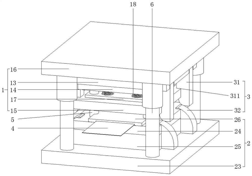
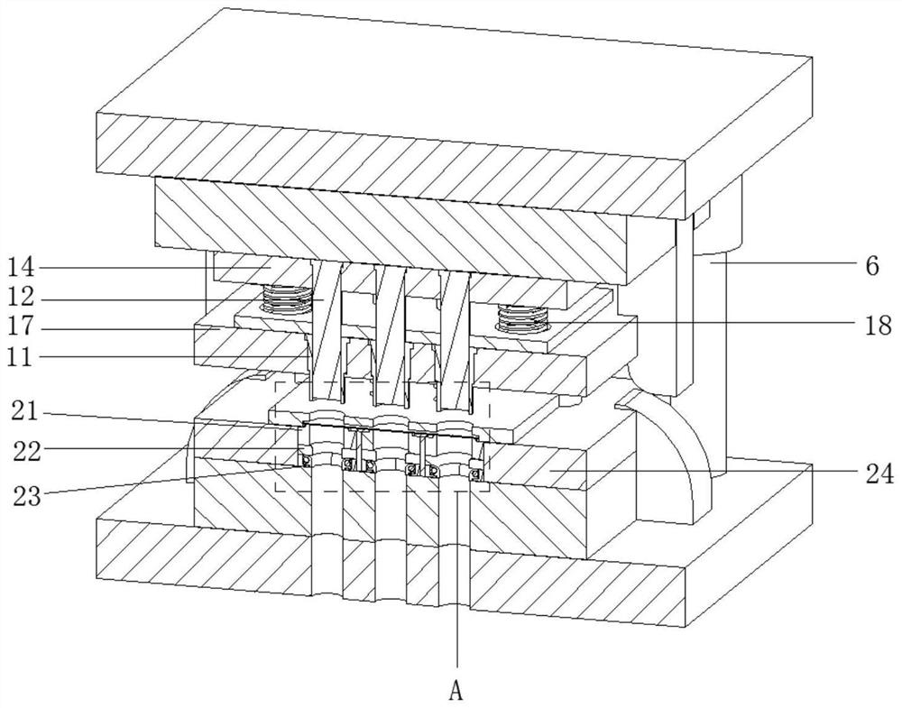
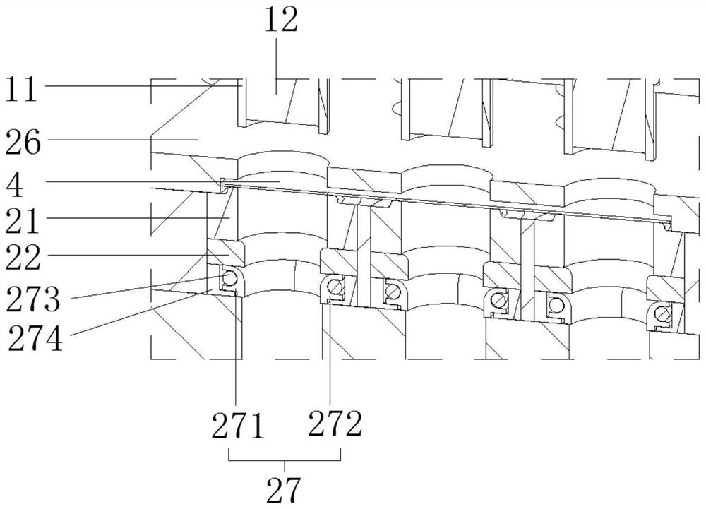
[0046] see Figure 1 to Figure 9 , in this embodiment, a one-time forming die for stamping button face parts, including:

[0047] Upper die 1, the upper die 1 is provided with a punching sleeve 11 and a punching insert 12, the punching sleeve 11 is coaxially sleeved on the punching insert 12;

[0048] Lower die 2. The lower die 2 is provided with a first insert 21 and a second insert 22 in sequence along the punching direction. The sl...


PUM


Abstract

The invention discloses a one-step forming die for stamping a button surface piece, which comprises an upper die, a lower die, a lower die, a lower die, a punching sleeve and a punching insert pin, the upper die is provided with a punching sleeve and a punching insert pin, and the punching sleeve is coaxially sleeved on the punching insert pin; a first insert and a second insert are sequentially arranged on the lower die in the punching direction; and the limiting assembly can enable the punching insert pin to move or be static relative to the blanking sleeve. The punching sleeve and the punching insert pin which are coaxially designed can be used for manufacturing a finished product through single-time mold closing, so that the machining time is saved, the first insert and the second insert are sequentially arranged in the material punching direction, the utilization rate of the mold machining area is increased, more forming holes can be designed in the unit area, the machining number of products can be increased, and the machining efficiency is improved. Compared with the prior art, more products can be processed within shorter time.

Description

technical field [0001] The invention relates to the technical field of stamping dies, in particular to a one-step forming die for stamping button face parts. Background technique [0002] The longitudinal section of the button face piece is in the shape of "凵", which is used to cover the end face of the button, and is made by punching a sheet with a punching die. In the prior art, the method of using a stamping die to process includes the first step of punching out the sheet body and making a circular embryonic body sheet, and the second part is bending and forming and making a finished workpiece in the shape of "凵". The product can only be obtained by opening two acupoints on the mold and closing the mold twice, which has the following shortcomings: (1) Two inserts need to be arranged corresponding to the two acupoints, one for punching out a circular blank sheet, the other One is used for bending and forming a finished workpiece in the shape of "凵", which requires a large...

Claims


Application Information

Patent Timeline
Patent Type & Authority Applications(China)
IPC IPC(8): B21D35/00B21D37/10B21D37/08B21D53/48
CPCB21D35/002B21D37/10B21D37/08B21D53/48Y02E60/10
Inventor 赵奉明张轩涵胡国平
Owner 东莞市钮纽实业有限公司
Why Eureka
Try Eureka