Method for Preparing a Yarn End for Spinning in at a Rotor Spinning Device of a Rotor Spinning Machine along with a Rotor Spinning Machine

A rotor spinning machine and rotor spinning technology, applied in the field of yarn ends, can solve the problems of different processing quality of yarn ends, achieve the effect of improving machine efficiency, improving yarn quality, and increasing success rate

Active Publication Date: 2017-08-01
RIETER INGOLSTADT GMBH
View PDF8 Cites 8 Cited by
  • Summary
  • Abstract
  • Description
  • Claims
  • Application Information

AI Technical Summary

Problems solved by technology

Here, however, differences in the quality of the yarn end processing can occur with respect to the length of the yarn end and fiber unraveling

Method used


Image

  • Method for Preparing a Yarn End for Spinning in at a Rotor Spinning Device of a Rotor Spinning Machine along with a Rotor Spinning Machine
  • Method for Preparing a Yarn End for Spinning in at a Rotor Spinning Device of a Rotor Spinning Machine along with a Rotor Spinning Machine
  • Method for Preparing a Yarn End for Spinning in at a Rotor Spinning Device of a Rotor Spinning Machine along with a Rotor Spinning Machine

Examples


Embodiment Construction

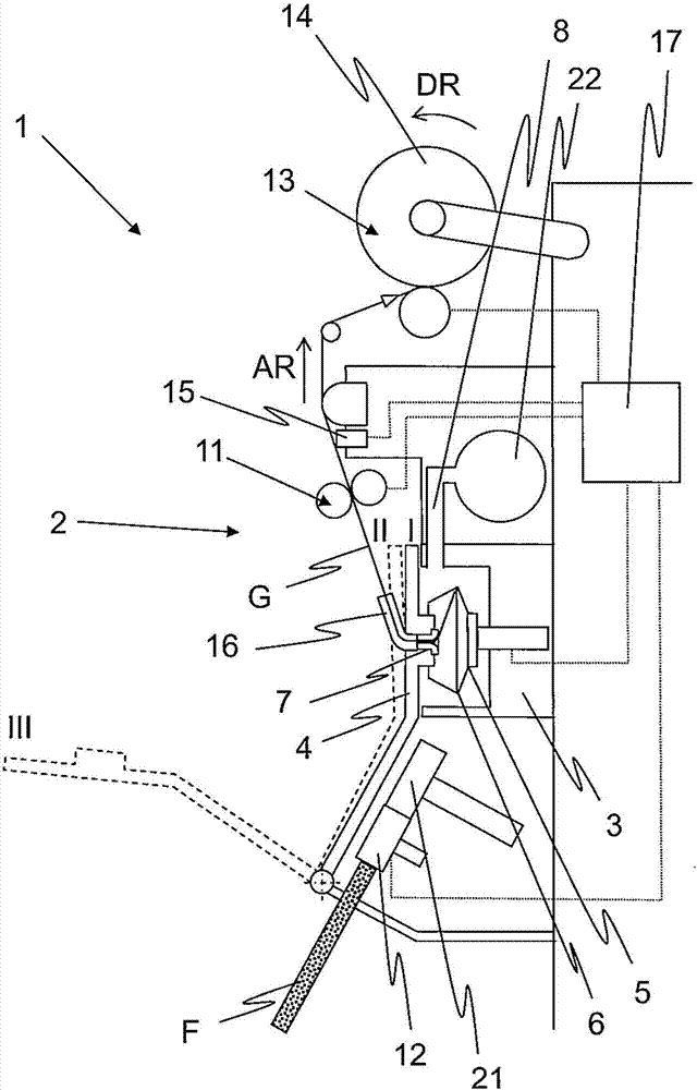
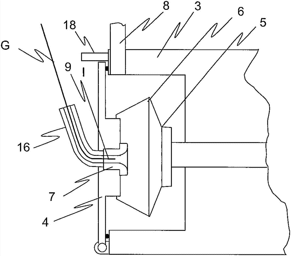
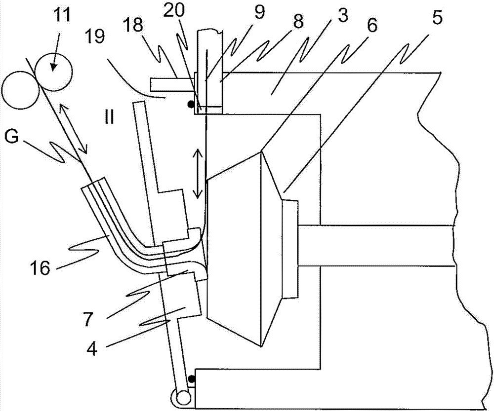
[0034] figure 1 The rotor spinning device 2 of the rotor spinning machine 1 is shown in a schematic sectional view. The rotor spinning device 2 generally has a rotor housing 3 in which the spinning rotor 5 is rotatably supported and operates at an operating speed during the operation of the rotor spinning device 2. The fiber material F to be spun into yarn is conveyed to the spinning rotor 5 through the feeding device 12 and the opening device 21 (where it is opened into a single fiber) and falls on the fiber of the spinning rotor 5 in the form of a fiber ring. In the coacervation tank 6. From here, the fiber material is incorporated into the end of the yarn G produced in the rotor spinning device 2. The yarn produced in the spinning rotor 5 is drawn in the same known manner by means of a drawing device 11 formed here by two drawing rollers through a drawing nozzle 7 and is wound by means of a winding device 13 On the bobbin 14. The rotor housing 3 is coupled to the central ...


PUM


Abstract

With a method for preparing a yarn end (9) for spinning in at a rotor spinning device (2) of a rotor spinning machine (1) with a rotor housing (3) that can be closed with a cover (4) and can be subjected to negative pressure through a negative pressure channel (8), with a spinning rotor (5) that is rotatably mounted in the rotor housing (3) and rotates with an operating rotational speed during the spinning operation along with a draw-off nozzle (7), the yarn end (9) to be prepared is introduced into the negative pressure channel (8), and is interrupted by a severing structure (10) of the open edge of the rotating spinning rotor (5), and is thereby prepared for spinning in. During the interruption of the yarn end (9), the spinning rotor (5) is driven with a defined rotational speed for the preparation of the yarn end, whereas the rotational speed for the preparation of the yarn end is either equal to the operating rotational speed of the spinning rotor (5) or is less than the operating rotational speed of the spinning rotor (5). A corresponding rotor spinning machine (1) features a control unit (17), by means of which the rotor spinning device (2) can be operated in accordance with one of the preceding claims.

Description

Technical field [0001] The present invention relates to a method for preparing yarn ends for piecing at a rotor spinning device of a rotor spinning machine, wherein the rotor spinning machine has a cover that can be closed and can pass negative pressure The channel is loaded with a rotor housing under negative pressure, a spinning rotor (ie, a rotor) that is rotatably supported in the rotor housing and runs at an operating speed during spinning operation, and a drawing nozzle. In this method, the yarn end to be prepared is introduced into the negative pressure channel of the rotor spinning device, and is cut by the breaking structure of the open edge of the rotating spinning rotor and thus is prepared for splicing. The invention also relates to a corresponding rotor spinning machine having at least one such rotor spinning device. Background technique [0002] In order to start the spinning process at the rotor spinning machine during spinning, or to interrupt the spinning proces...

Claims


Application Information

Patent Timeline
Patent Type & Authority Applications(China)
IPC IPC(8): D01H4/50D01H4/08D01H4/48
CPCD01H4/08D01H4/48D01H4/50
Inventor F·拜尔J·彭罗彭斯基M·弗克尔J·库特尔瓦斯尔
Owner RIETER INGOLSTADT GMBH
Why Eureka
Try Eureka