Fuse block with improved unidirectional operator

a technology of unidirectional operator and fuse block, which is applied in the direction of contact mechanism, mechanical control device, instruments, etc., can solve the problems of requiring modification of existing fuse block, and achieve the effects of reducing shear force, preventing shearing of ridges, and high torqu

Active Publication Date: 2008-01-01
ROCKWELL AUTOMATION TECH
View PDF8 Cites 21 Cited by
  • Summary
  • Abstract
  • Description
  • Claims
  • Application Information

AI Technical Summary

Benefits of technology

[0014]The present invention provides an improved uni-directional mechanism using balls selectively locking a track and drive for one direction of motion. The present inventors have recognized that control of the contact surfaces to the ball, ideally to be parallel tangents, can significantly reduce shear force on the ridges of the track, preventing shearing of the ridges under high torque. By reducing shear forces, the ridges may be shaped for improved passage of the balls when locking of the track and drive is not required.

Problems solved by technology

While this apparatus is suitable for its intended purpose, the mechanism requires modification of an existing fuse block.

Method used


Image

  • Fuse block with improved unidirectional operator
  • Fuse block with improved unidirectional operator
  • Fuse block with improved unidirectional operator

Examples


Embodiment Construction

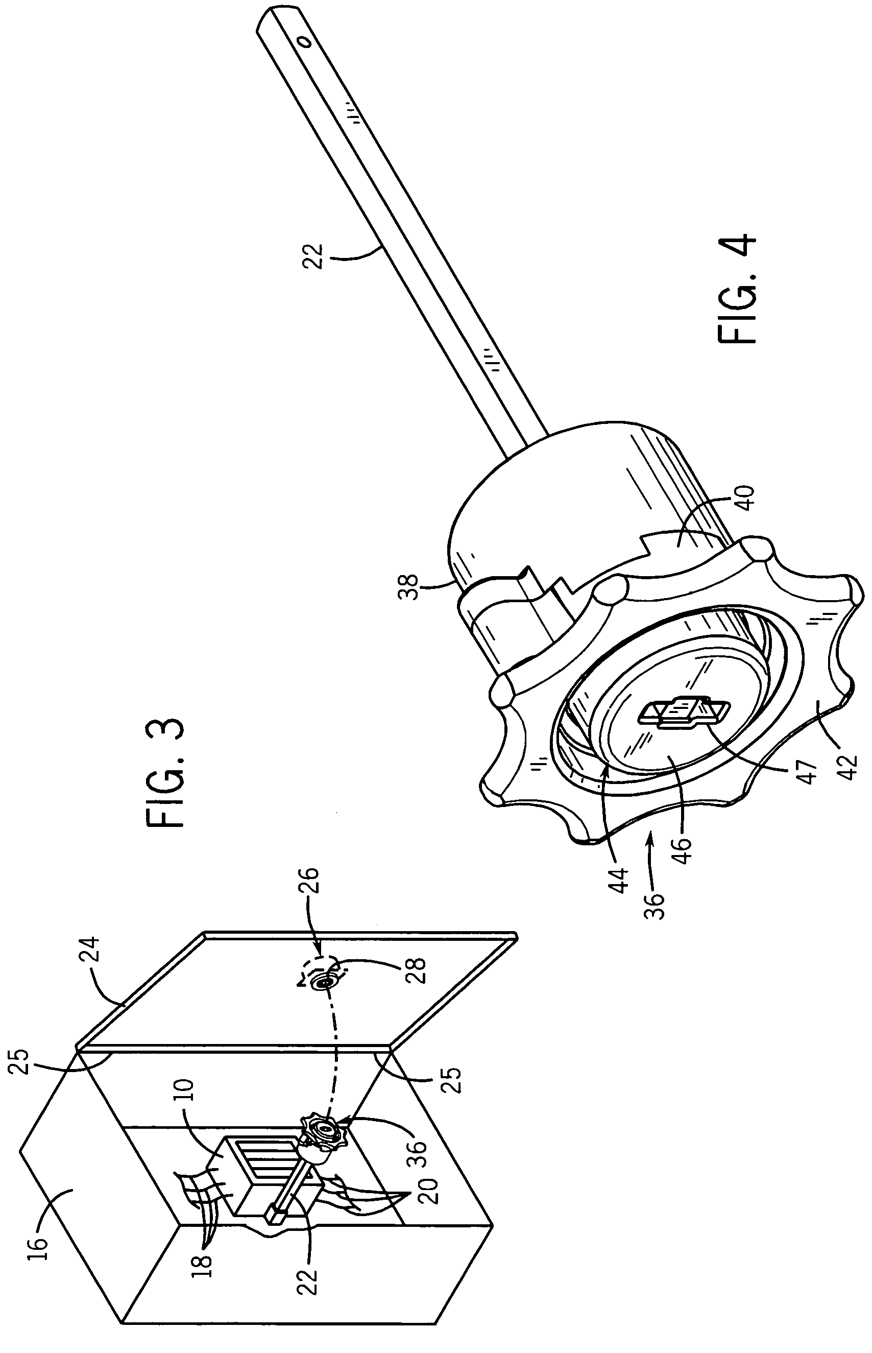
[0054]Referring to FIGS. 3 and 4, the present invention modifies the fuse block 10 described above by mounting an operator assembly 36 to the axially outer end of a rotary shaft 22 coupled to the fuse block 10. While an exemplary embodiment of the present invention is described of controlling electrical current through fuse block, it should be appreciated that the present invention is applicable to any electrical disconnect, including fuses, circuit breakers, and traditional switches.

[0055]Operator assembly 36 extends generally axially, and interfaces with door knob 26 and, in particular, with connector 28. Operator assembly 36 is thus operable by a user to connect power to fuses on fuse block 10, and disconnect power from fuse block 10. Operator assembly 36 preferably comprises a plastic, though one skilled in the art will recognize that any material suitable to withstand the stress and strain experienced during operation falls within the scope of the present invention.
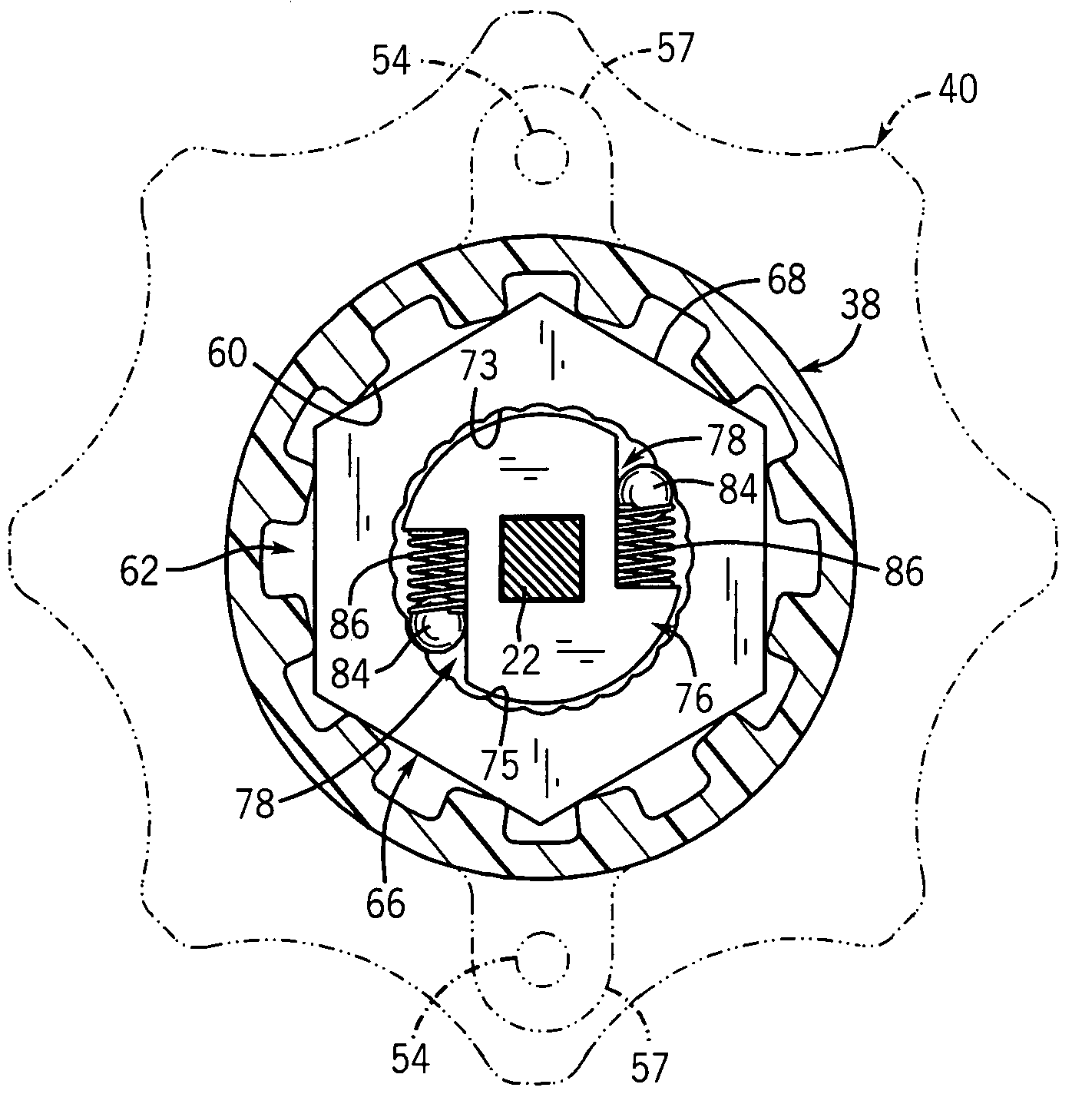
[0056]Referr...


PUM


Abstract

A ball ratchet mechanism suitable for use with an electrical disconnect employs a track and drive surface that engage the ball so as to capture it without significant shear force being applied to ridges of the track. In this way, the shape of the track can be optimized for smooth ratcheting action without the risk of high torques shearing track ridges.

Description

CROSS-REFERENCE TO RELATED APPLICATIONS[0001]—STATEMENT REGARDING FEDERALLY SPONSORED RESEARCH OR DEVELOPMENT[0002]—BACKGROUND OF THE INVENTION[0003]The present invention relates to a unidirectional mechanism useful in electrical disconnects and in particular to a unidirectional mechanism providing smooth rotation and high strength.[0004]Referring to FIG. 1, a disconnect in the form of a standard fuse block 10 of the prior art may receive fuse cartridges 12 along its front face and may attach at its rear face to the rear wall 14 of a metal cabinet 16.[0005]Input terminals along the top of fuse block 10 may receive wires 18 which connect independently to one side of each fuse cartridge 12, the latter which interconnect wires 18 to wires 20 attached to output terminals along the bottom of the fuse cartridge 12. Wires 18, for example, may be connected to a source of three-phase power and wires 20, for example, may be connected to a motor or other piece of equipment.[0006]Fuse block 10 ...

Claims


Application Information

Patent Timeline
Patent Type & Authority Patents(United States)
IPC IPC(8): H01H3/20G05G5/06
CPCH01H3/50Y10T74/2133Y10T74/20636H01H9/226
Inventor HOUCK, III, THEODORE JOHNNING, JIEMILLER, JAMES PETER
Owner ROCKWELL AUTOMATION TECH
Why Eureka
Try Eureka