Universal furnace-passing jig of jointed board structure
A technology of passing furnace and jig, applied in the direction of manufacturing tools, final product manufacturing, welding equipment, etc., can solve the problems of low production efficiency, time-consuming production, and high defect rate.
- Summary
- Abstract
- Description
- Claims
- Application Information
AI Technical Summary
Problems solved by technology
Method used
Image
Examples
Embodiment 1
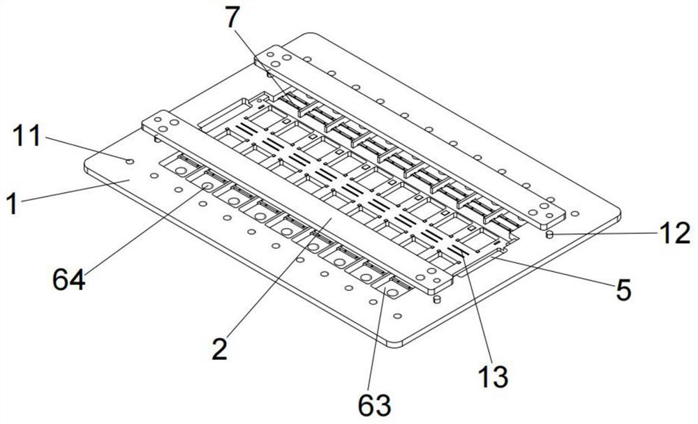
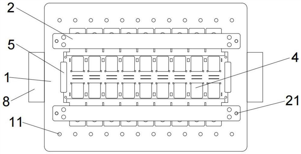
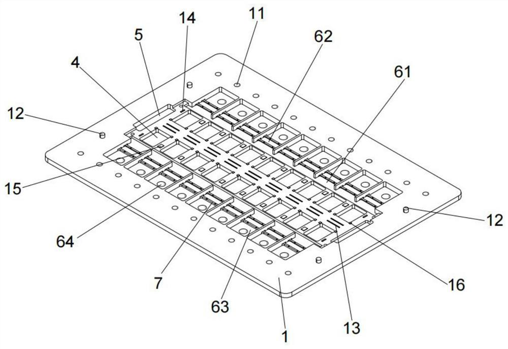
[0043] The embodiment of the present invention provides a general furnace passing jig with a panel structure, such as Figure 1-5 As shown, it includes a substrate 1 and a cover strip 2, and the cover strip 2 and the substrate 1 are distributed up and down. Between the substrate 1 and the cover strip 2, photoelectric module products 3 of different thicknesses are placed. A support block group is provided, and the support block group is used to support the optoelectronic module product 3;
[0044] The base plate 1 includes a product carrying area, the product carrying area is arranged in the upper center area of the base plate 1, the product carrying area includes a product rack area and a product groove area, and the product rack area is provided with a support block group, The product groove area includes several first grooves 4, several second grooves 6 and several third grooves 5;
[0045] The base plate 1 further includes a positioning and fixing area, which is arranged...
Embodiment 2
[0059] On the basis of Example 1, as Figure 6-7 As shown, the left and right ends of the base plate 1 are symmetrically provided with a pressing mechanism, and the pressing mechanism includes:
[0060] Mounting seat 8, the lower part of the mounting seat 8 is fixedly connected with the base plate 1, the upper part of the mounting seat 8 is installed with a motor 81 on the side close to the base plate 1, and the motor 81 is fixedly connected with the connecting shaft 82, the said A groove one 83 is symmetrically arranged at the front and rear ends of the cylindrical section of the connecting shaft 82, and a spring one 84 is fixed inside the groove one 83, and the spring one 84 is fixedly connected with the magnetic block 85;
[0061] A movable slot 817, the movable slot 817 is arranged at the upper and lower ends of the mounting seat 8, and the movable slot 817 is arranged corresponding to the motor 81;
[0062] Connecting block 86, the connecting block 86 is arranged inside ...
Embodiment 3
[0071] On the basis of Example 1, as Figure 8 As shown, a connection mechanism is fixed in the fixing hole 21, and the connection mechanism includes:
[0072] Fixing shell 9, the fixing shell 9 is fixedly arranged inside the fixing hole 21, the middle of the lower end of the fixing shell 9 is provided with a matching cavity 91, and the left and right sides of the matching cavity 91 are symmetrically provided with a through hole 912 And through hole 2, and through hole 2 and through hole 1 912 are distributed up and down, the inner left and right sides of the fixed shell 9 are symmetrically provided with power chambers 92, and the matching cavity 91 passes through through hole 1 912, through hole 2 and all The power chamber 92 is connected;
[0073] The pressing block 98 is fixedly connected with the fixed block 99 , the fixed block 99 is fixedly connected with the movable end of the telescopic rod 910 , and a spring is fixed between the fixed block 99 and the side wall of th...
PUM
 Abstract
Description
Claims
Application Information
 - R&D
- Intellectual Property
- Life Sciences
- Materials
- Tech Scout
- Unparalleled Data Quality
- Higher Quality Content
- 60% Fewer Hallucinations
Browse by: Latest US Patents, China's latest patents, Technical Efficacy Thesaurus, Application Domain, Technology Topic, Popular Technical Reports.
© 2025 PatSnap. All rights reserved.Legal|Privacy policy|Modern Slavery Act Transparency Statement|Sitemap|About US| Contact US: help@patsnap.com


