
Movable automatic charging device running in parking garage and used for charging electric vehicle

An automatic charging device, electric vehicle technology, applied in the direction of electric vehicle charging technology, electric vehicles, charging stations, etc., can solve the problems of long waiting time for charging stations, limited number of charging piles, inconvenient charging and use, etc., to achieve occupancy Small space, easy to charge and use, and easy to use

Pending Publication Date: 2022-08-05
上海林玺智能科技有限公司
View PDF0 Cites 0 Cited by
  • Summary
  • Abstract
  • Description
  • Claims
  • Application Information

AI Technical Summary

Problems solved by technology

[0002] With the rapid development of the global economy and the continuous improvement of people's living standards, the country is now vigorously calling for energy conservation and emission reduction. New energy electric vehicles (referred to as "electric vehicles") are being popularized and promoted on a large scale. People who respond to the call to buy new energy electric vehicles There are also more and more people who choose green travel, and electric vehicles must use batteries. However, due to the lack of comprehensive popularization of energy replacement stations, the waiting time for charging at charging stations is long, and the number of charging piles is limited. Electric vehicles need to queue up for charging. If there is no power during driving, it will stop halfway, which is inconvenient to charge and use

Method used


Image

  • Movable automatic charging device running in parking garage and used for charging electric vehicle
  • Movable automatic charging device running in parking garage and used for charging electric vehicle
  • Movable automatic charging device running in parking garage and used for charging electric vehicle

Examples


Embodiment Construction

[0015] The technical solutions in the embodiments of the present invention will be clearly and completely described below with reference to the accompanying drawings in the embodiments of the present invention. Obviously, the described embodiments are only a part of the embodiments of the present invention, but not all of the embodiments.

[0016] In the description of the present invention, it should be understood that the terms "upper", "lower", "front", "rear", "left", "right", "top", "bottom", "inside", " The orientation or positional relationship indicated by "outside" is based on the orientation or positional relationship shown in the accompanying drawings, and is only for the convenience of describing the present invention and simplifying the description, rather than indicating or implying that the indicated device or element must have a specific orientation, so as to The specific orientation configuration and operation are therefore not to be construed as limitations of...


PUM


Abstract

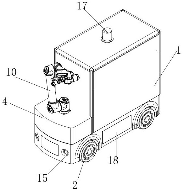
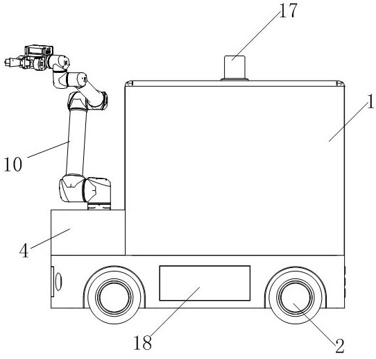
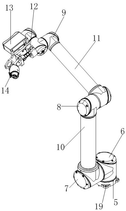
The movable automatic charging device comprises a vehicle body and the like, wheels are located at the bottom end of the vehicle body, a battery is located in the vehicle body, a vehicle head is located at the front end of the vehicle body, a base is fixed to the top end of the vehicle head, a first rotating part is installed on the base, and a second rotating part is connected with the first rotating part. The two ends of the first mechanical arm are connected with the second rotating piece and the third rotating piece respectively, the two ends of the second mechanical arm are connected with the third rotating piece and the fourth rotating piece respectively, the support is connected with the fourth rotating piece, and the camera and the discharging plug are installed on the fourth rotating piece and electrically connected with the battery. The electric bicycle is small in occupied space, convenient to charge and use, capable of supplying power to the electric bicycle in time and not limited by positions.

Description

technical field [0001] The invention relates to a charging device, in particular to a movable automatic charging device that operates in a parking garage to charge an electric vehicle. Background technique [0002] With the rapid development of the global economy and the continuous improvement of people's living standards, the current state is vigorously calling for energy conservation and emission reduction. New energy electric vehicles (referred to as "electric vehicles") are being popularized and promoted on a large scale. People who respond to the call to buy new energy electric vehicles More and more, electric vehicles must use batteries when choosing green travel. However, due to the lack of full popularization of energy swap stations, charging stations have a long waiting time, the number of charging piles is limited, and electric vehicles need to queue for charging. If there is no electricity during driving, it will stop halfway, which is inconvenient to charge and u...

Claims


Application Information

Patent Timeline
Patent Type & Authority Applications(China)
IPC IPC(8): B60L53/37B60L53/16B60L53/53B60P3/00
CPCB60L53/37B60L53/16B60L53/53B60P3/00Y02T90/14
Inventor 叶青林
Owner 上海林玺智能科技有限公司
Learn More