
Electronic device

A technology for electronic equipment and sound-generating units, which is applied to electrical components, telephone structures, sensors, etc., can solve the problems of rocking vibration abnormal sound, increased nonlinear distortion, and the impact of the casing on the use experience, etc., to achieve good stereo effects, improve The effect of privacy protection effect

Pending Publication Date: 2022-08-05
GOERTEK INC
View PDF0 Cites 0 Cited by
  • Summary
  • Abstract
  • Description
  • Claims
  • Application Information

AI Technical Summary

Problems solved by technology

At this time, when the two sets of vibration systems in the double-sided sounding monomer perform large-amplitude vibrations, a large airflow impact will be generated and impact the casing of the electronic device, which will cause a more obvious vibration of the casing and affect the use. to experience
In addition, since the two sets of vibration systems share an acoustic back cavity, when each is working, the airflow will interfere with each other when flowing in the shared acoustic back cavity, which also affects the vibration state of each vibration system and causes nonlinearity A series of problems, such as increased distortion, shaking vibration and abnormal sound, have affected the final sound effect

Method used


Image

  • Electronic device
  • Electronic device
  • Electronic device

Examples


Embodiment Construction

[0041] The technical solutions in the embodiments of the present invention will be clearly and completely described below with reference to the accompanying drawings in the embodiments of the present invention. Obviously, the described embodiments are only a part of the embodiments of the present invention, but not all of the embodiments. Based on the embodiments of the present invention, all other embodiments obtained by those of ordinary skill in the art without creative efforts shall fall within the protection scope of the present invention.

[0042] It should be noted that all directional indications (such as up, down, left, right, front, back...) in the embodiments of the present invention are only used to explain the relationship between various components under a certain posture (as shown in the accompanying drawings). The relative positional relationship, the movement situation, etc., if the specific posture changes, the directional indication also changes accordingly. ...


PUM


Abstract

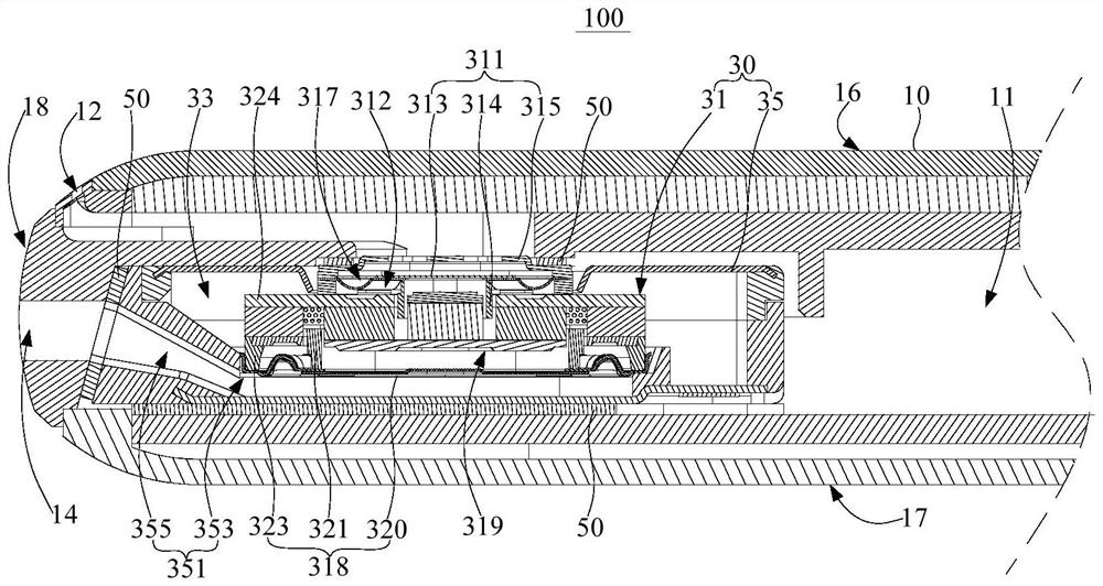
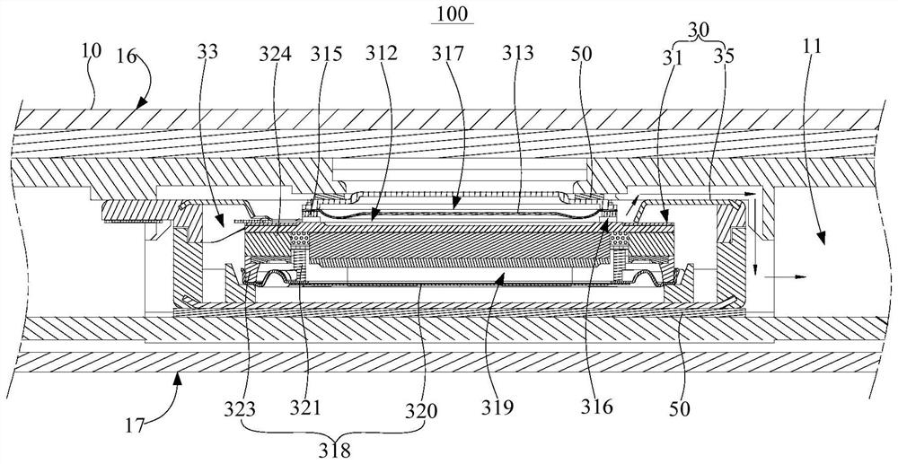
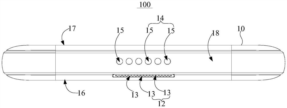
The invention discloses electronic equipment. The electronic equipment comprises a shell and a sound production module, a mounting cavity is formed in the machine shell. The sound production module is arranged in the mounting cavity and comprises a sound production unit, the sound production unit comprises a first sound production unit and a second sound production unit, the first sound production unit and the second sound production unit are arranged back to back, the orthographic projection area of the first sound production unit is smaller than that of the second sound production unit, and the first sound production unit is provided with a first rear cavity; the second sound production unit is provided with a second rear cavity, and the second rear cavity and the first rear cavity are arranged in an isolated mode. Wherein the first rear cavity is communicated with the mounting cavity, the sound production module is further provided with an expansion cavity, and the expansion cavity is communicated with the second rear cavity and is isolated from the first rear cavity; the casing is provided with a first sound outlet hole and a second sound outlet hole corresponding to the first sound production unit and the second sound production unit respectively. According to the technical scheme, the electronic equipment can be prevented from generating a vibration sense in the sound production process, and meanwhile the sound production effect can be guaranteed.

Description

technical field [0001] The invention relates to the technical field of electro-acoustic energy conversion, and in particular, to an electronic device. Background technique [0002] At present, in order to make an electronic product (such as a mobile phone) in the related art have a better stereo effect when it is in the loudspeaker outgoing mode, and have a better privacy protection effect when it is in the handset call mode. Usually, a double-sided sounding monomer is directly used in the audio system of electronic products, so as to emit two sound waves with the same phase for superposition enhancement to improve the stereo effect of the speaker in the external mode, or based on the acoustic dipole effect. Two sound waves with opposite phases are emitted to cancel and attenuate to improve the privacy protection effect in the handset call mode. [0003] However, when using the above-mentioned solution, there will be major drawbacks. Specifically, the two sets of vibration...

Claims


Application Information

Patent Timeline
IPC IPC(8): H04M1/03H04R9/02H04M1/02
CPCH04R9/027H04R9/025H04M1/035H04M1/026
Inventor 蔡晓东刘松郎贤忠张成飞刘春发
Owner GOERTEK INC
Learn More