Conveying device

A conveying device and mounting frame technology, applied in the direction of transportation and packaging, conveyor objects, rollers, etc., can solve the problems of excessive production time, occupation, and increased transportation costs of semi-finished parts, so as to save production and operation costs and save transportation the effect of time

Active Publication Date: 2022-08-09
浙江安升吉达精密科技有限公司
View PDF10 Cites 0 Cited by
  • Summary
  • Abstract
  • Description
  • Claims
  • Application Information

AI Technical Summary

Problems solved by technology

[0004] The object of the present invention is to address the deficiencies of the prior art, and propose a conveying device, which is used to solve the prior art mentioned in the background technology that two kinds of conveying devices need to be used respectively to realize the horizontal and vertical transport and transfer of the semi-finished parts of the air rod, As a result, the transportation cost of semi-finished parts is increased and the technical problem of this transportation method takes up more production time

Method used


Image

  • Conveying device
  • Conveying device
  • Conveying device

Examples


Embodiment Construction

[0017] The technical solutions in the present invention will be further described below with reference to the accompanying drawings and embodiments.

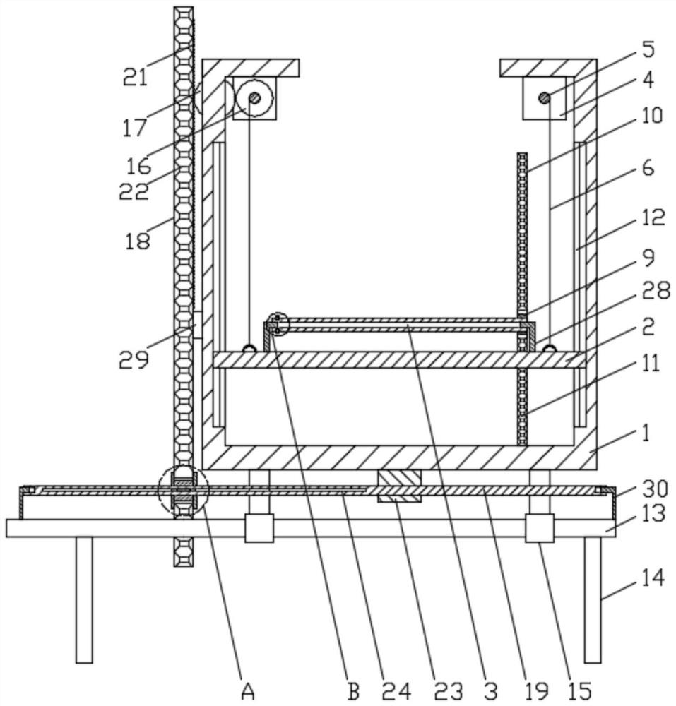
[0018] like figure 1 As shown, a conveying device includes: a mounting frame 1, a sliding plate 2, a driving unit and a row of horizontal rollers 3. The sliding plate 2 is slidably connected with the mounting frame 1 and can slide vertically reciprocatingly along the mounting frame 1. The frame 1 is provided with two vertical and opposite first chutes 12, two ends of the sliding plate 2 respectively extend into the two first sliding grooves 12, and the ends of the sliding plate 2 correspond to the corresponding first sliding grooves 12. 12 Sliding connections. The drive unit is arranged on the mounting frame 1 and is connected with the sliding plate 2 as the power to drive the sliding plate 2 to slide. A row of rollers 3 are rotatably arranged on the upper part of the sliding plate 2, and the same end of the row of rollers 3 is...


PUM


Abstract

A conveying device is used for solving the technical problems that in the prior art, two conveying devices need to be adopted for horizontally and vertically conveying and transferring air rod semi-finished product components, so that the conveying cost of the semi-finished product components is increased, and the conveying mode occupies much production time. Comprising a mounting frame, a sliding plate, a driving unit and a row of horizontal rollers, the sliding plate is in sliding connection with the mounting frame and can vertically slide back and forth along the mounting frame, the driving unit is arranged on the mounting frame and serves as power for driving the sliding plate to slide to be connected with the sliding plate, and the row of rollers are rotationally arranged on the upper portion of the sliding plate. The same ends of the row of rollers are connected with first connecting assemblies which drive the row of rollers to rotate synchronously at the same time, a second connecting assembly is arranged between the other end of one roller and the mounting frame, and the second connecting assembly is used for driving the roller to rotate along with sliding of the sliding plate, so that the other rollers rotate synchronously. The device is mainly used for conveying semi-finished parts.

Description

technical field [0001] The invention relates to the technical field of air rod processing, in particular to a conveying device. Background technique [0002] The gas rod is a telescopic rod structure that can be retracted. The gas rod generally includes a cylindrical shell and a push-pull rod that is inserted in the shell and can slide along the shell. During the production process of the gas rod, the production personnel must separately produce and process the shell and push Pull the rod, and then assemble the shell and the push-pull rod. Here, the shell and the push-pull rod are collectively referred to as semi-finished parts. [0003] In the production process of semi-finished parts, the production personnel need to transport and transfer the semi-finished parts frequently. Sometimes it is necessary to carry out horizontal transportation and transfer first, and then carry out vertical lifting and transportation. Therefore, the manufacturer needs to manufacture and process...

Claims


Application Information

Patent Timeline
Patent Type & Authority Applications(China)
IPC IPC(8): B65G13/06B65G47/57
CPCB65G13/06B65G47/57
Inventor 姚根法
Owner 浙江安升吉达精密科技有限公司
Why Eureka
Try Eureka