

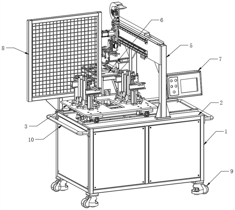
Hardware machining robot stamping line material frame
A robot and stamping line technology, applied in the field of metal workpiece stamping, can solve the problems of reduced work efficiency, low efficiency, poor product quality stability, etc., to achieve the effect of improving protection performance, enhancing practicability, and reducing labor
- Summary
- Abstract
- Description
- Claims
- Application Information
AI Technical Summary
Problems solved by technology
Method used
Image

Examples
Embodiment Construction
[0025] The technical solutions of the present invention will be clearly and completely described below with reference to the accompanying drawings. In the description of the present invention, it should be noted that the terms "center", "upper", "lower", "left", "right", "vertical", "horizontal", "inner", "outer", etc. The indicated orientation or positional relationship is based on the orientation or positional relationship shown in the accompanying drawings, which is only for the convenience of describing the present invention and simplifying the description, rather than indicating or implying that the indicated device or element must have a specific orientation or a specific orientation. construction and operation, and therefore should not be construed as limiting the invention. Furthermore, the terms "first", "second", and "third" are used for descriptive purposes only and should not be construed to indicate or imply relative importance.
[0026] In the description of the...
PUM
 Abstract
Description
Claims
Application Information