Radioactive ion distribution device

A dispensing device and radioactive technology, applied in the field of imaging, can solve problems such as waste, inconvenient distribution of radioactive ions, and increased risk of exposure, etc., to achieve convenient blowing direction, convenient continuous feeding, convenient quantitative feeding and blowing Effect

Pending Publication Date: 2022-03-01
天津中核永泰科技有限公司
View PDF0 Cites 0 Cited by
  • Summary
  • Abstract
  • Description
  • Claims
  • Application Information

AI Technical Summary

Problems solved by technology

[0003] The radioactive ion dispensing device proposed by the present invention solves the problem that the existing radioactive ions are inconvenient to distribute, easily cause waste, and increase the risk of exposure

Method used


Image

  • Radioactive ion distribution device
  • Radioactive ion distribution device
  • Radioactive ion distribution device

Examples


Embodiment 1

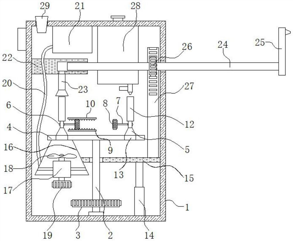
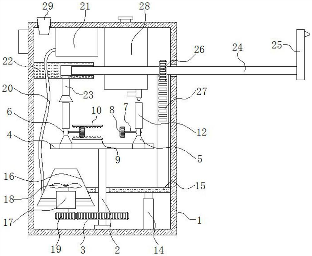
[0028] refer to figure 1 and Figure 4-6 : Radioactive ion distribution device, comprising isolation box 1, the bottom inner wall of isolation box 1 is rotatably connected with material receiving mechanism, the top of material receiving mechanism is provided with the liquid storage tank 28 fixedly connected with the top inner wall of isolation box 1, on the material receiving mechanism A first steering gear 3 is provided;

[0029] The left side of the material receiving mechanism is provided with a blowing mechanism, and the blowing mechanism drives the material receiving mechanism to rotate through the first steering gear 3, the blowing mechanism is connected with an air intake pipe 20, and the top of the air intake pipe 20 is connected with a nitrogen tank 21, and The nitrogen tank 21 is fixedly arranged on the top inner wall of the isolation box 1;

[0030] The right side of the material receiving mechanism is provided with a lifting and allocating mechanism, the lifting ...

Embodiment 2

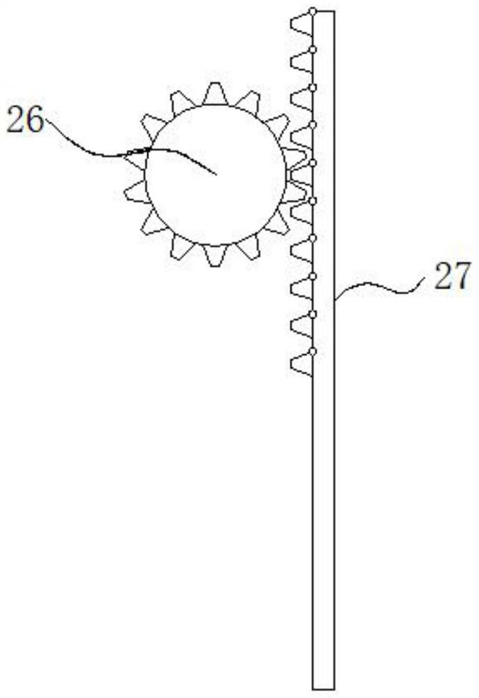
[0035] refer to Figure 1-3 : radioactive ion distribution device, wherein the blowing mechanism includes a fixed cover 16, the inner wall of the fixed cover 16 is fixedly connected with a biaxial motor 17, the top output shaft of the biaxial motor 17 is fixedly connected with a fan blade 18, the bottom of the biaxial motor 17 The output shaft is fixedly connected with a driving gear 19, and the driving gear 19 is meshed with the first steering gear 3 for transmission, the intake pipe 20 communicates with the fixed cover 16, and the lifting and adjusting mechanism includes a push rod motor 14 fixedly connected with the bottom inner wall of the isolation box 1, The output shaft of push rod motor 14 is fixedly connected with lifting plate 15, and lifting plate 15 is fixedly connected with fixed cover 16, and the top right side of lifting plate 15 is fixedly connected with steering rack 27, and the front of steering rack 27 is provided with movable cover. Be located at the steeri...


PUM


Abstract

The invention discloses a radioactive ion distribution device, relates to the technical field of iconography, and provides the following scheme for solving the problems that existing radioactive ions are inconvenient to distribute, waste is easily caused, and the exposure risk is increased: the radioactive ion distribution device comprises an isolation box, and the inner wall of the bottom of the isolation box is rotatably connected with a material receiving mechanism; a liquid storage tank fixedly connected with the inner wall of the top of the isolation box is arranged above the material receiving mechanism, and a first steering gear is arranged on the material receiving mechanism. A blowing mechanism is arranged on the left side of the material receiving mechanism and drives the material receiving mechanism to rotate through a first steering gear, an air inlet pipe is connected to the blowing mechanism, and a nitrogen tank is connected to the top end of the air inlet pipe. According to the radioactive ion blowing device, quantitative material receiving and blowing can be conveniently carried out, close-range operation of medical staff is not needed, the safety of the medical staff is improved, the blowing-out direction of radioactive ions can be conveniently and automatically distributed, meanwhile, the device can be repeatedly used, and the automation degree and the integration degree of the device are improved.

Description

technical field [0001] The invention relates to the technical field of imaging, in particular to a radioactive ion distribution device. Background technique [0002] As the crown of imaging, nuclear medicine has outstanding advantages in detecting diseases such as tumors / heart / kidneys, but the development of basic targeted tracers is slow; major hospitals, research institutes and high-efficiency More and more attention is paid to the research and development of new drugs. However, it has the particularity of radioactivity, and it cannot be freely distributed like other reagents, and because the precursors used as raw materials are expensive, it is not only wasteful to use it for scientific research, but also increases the risk of exposure to researchers. To this end we propose a radioactive ion distribution device. Contents of the invention [0003] The radioactive ion distributing device proposed by the present invention solves the problems that the existing radioactive...

Claims


Application Information

Patent Timeline
Patent Type & Authority Applications(China)
IPC IPC(8): G21H5/02
CPCG21H5/02
Inventor 杜建光曹栋张微
Owner 天津中核永泰科技有限公司
Why Eureka
Try Eureka