Solar power generation equipment

A technology for power generation equipment and solar energy, applied in photovoltaic power generation, electrical components, photovoltaic modules, etc., can solve the problems of not being able to clean up automatically at regular intervals, easily damaging solar panels, affecting the power generation efficiency of equipment, etc., to achieve convenient control, easy interception, The effect of increasing the open range

Active Publication Date: 2021-03-30
浙江浦江裕恒五金制品有限公司
View PDF11 Cites 3 Cited by
  • Summary
  • Abstract
  • Description
  • Claims
  • Application Information

AI Technical Summary

Problems solved by technology

[0006] Aiming at the deficiencies of the prior art, the present invention provides a solar power generation device, which solves the problem of automatic cleaning that cannot be done regularly, thus affecting the power generation efficiency of the device. When encountering extreme weather, such as heavy snow or hail, the solar power is easily damaged. battery problem

Method used


Image

  • Solar power generation equipment
  • Solar power generation equipment
  • Solar power generation equipment

Examples


Embodiment 1

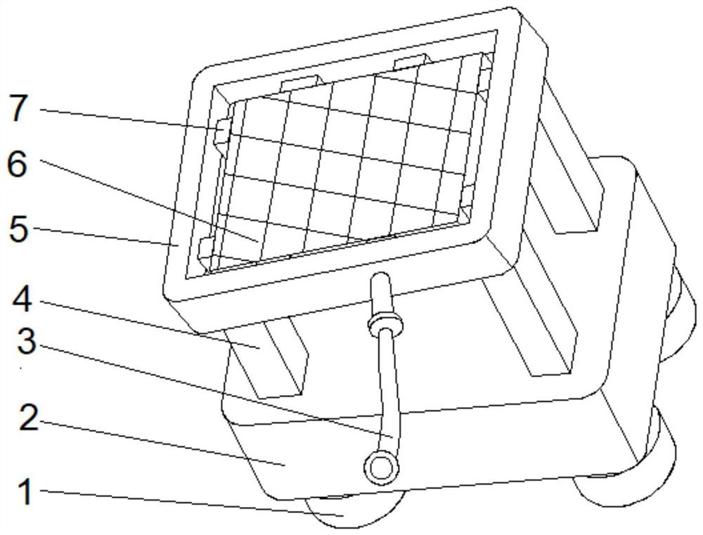
[0034] see Figure 1-2 , the present invention provides a technical solution: a solar power generation device, including a water storage tank 2, a support seat 1 is fixedly connected to both sides of the bottom of the water storage tank 2, and a linkage frame is fixedly connected to both sides of the top of the water storage tank 2 4. The top of the linkage frame 4 is provided with a cleaning device 5, the inner walls of both sides of the cleaning device 5 are fixedly connected with a fixed block 6, and the side of the fixed block 6 away from the cleaning device 5 is fixedly connected with a power generation board 7, and the water storage tank 2 The middle part of the front is communicated with a pipeline 3, and the end of the pipeline 3 away from the water storage tank 2 is fixedly connected with the cleaning device 5.

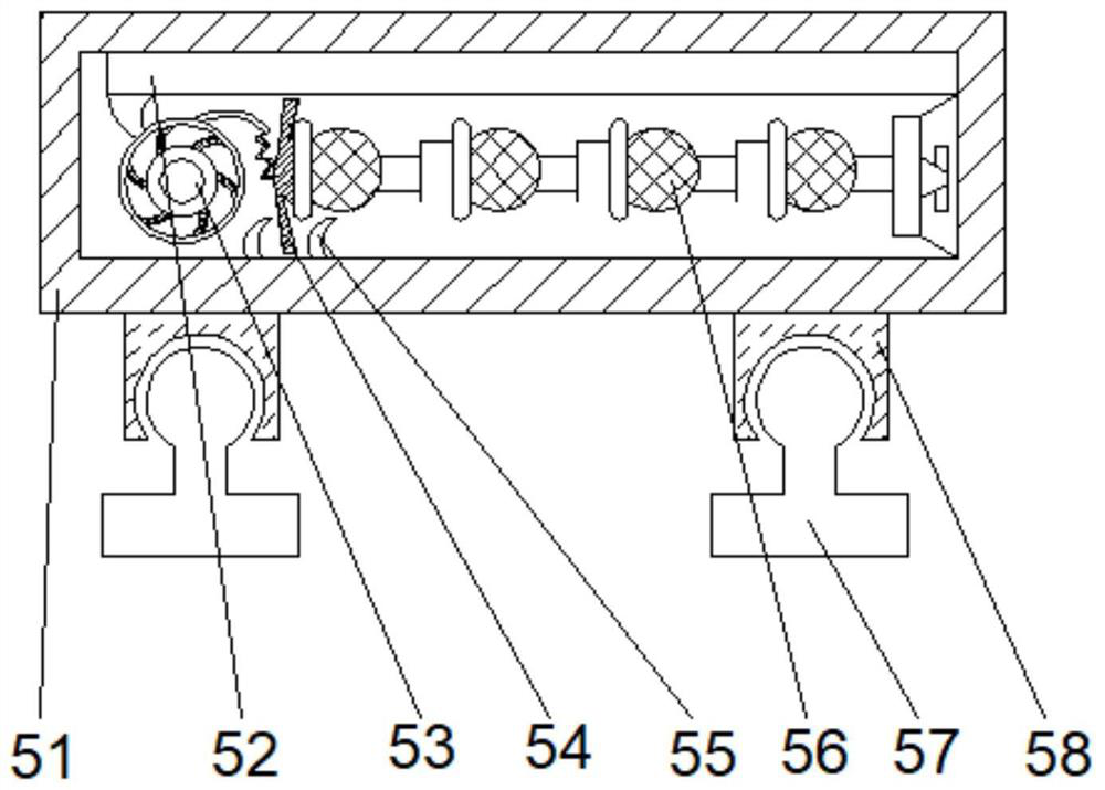
[0035]Wherein, cleaning device 5 comprises frame 51, and the bottom both sides of frame 51 is fixedly connected with recessed block 58, and the inner chamber...

Embodiment 2

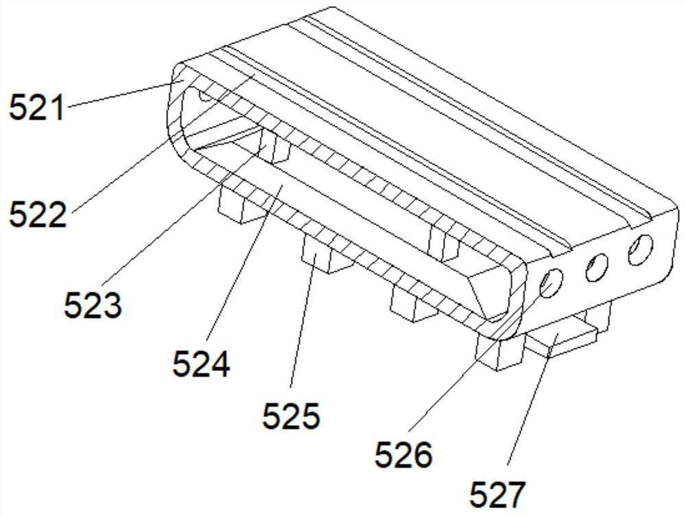
[0038] see Figure 1-4 On the basis of Embodiment 1, the present invention provides a technical solution: the cleaning mechanism 52 includes a baffle 521, a nozzle 527 is arranged at the middle of the bottom of the baffle 521, and the bottom of the baffle 521 is fixedly connected to both sides of the nozzle 527 There is a scraping mechanism 525, the top of the baffle 521 is provided with a chute 522, the bottom of the inner cavity of the baffle 521 is provided with a circulation box 524, and both sides of the top of the circulation box 524 are fixedly connected with fixed rods 523, and the two sides of the baffle 521 The side outer wall defines a through hole 526 .

[0039] Wherein, the scraping mechanism 525 includes an upper block d1, an adjustment block d2 is arranged at the middle position of the inner cavity bottom of the upper block d1, the bottom of the adjustment block d2 is fixedly connected with a bottom block d3, and the top two sides of the bottom block d3 are arra...

Embodiment 3

[0042] see Figure 1-6 , on the basis of Embodiment 1 and Embodiment 2, the present invention provides a technical solution: the auxiliary mechanism d5 includes a swing plate d51, the bottom of the swing plate d51 is provided with a blocking plate d52, and the top of the swing plate d51 is fixedly connected with a joint plate d53, the bottom of the inner cavity of the combination plate d53 is provided with a lower swing plate d54, and the right side of the top of the lower swing plate d54 is fixedly connected with a rebound piece d55.

[0043] Wherein, the lower swing plate d54 includes a bearing plate t1, the top of the bearing plate t1 is fixedly connected with a plate surface t2, the top of the bearing plate t1 is fixedly connected with a guide rod t4, and the bottom of the guide rod t4 is provided with a protruding ball t3.

[0044] When in use, the device reduces the impact force during the lifting process, and the plate surface t2 has the effect of increasing friction, s...


PUM


Abstract

The invention discloses solar power generation equipment which comprises a water storage tank, supporting bases are fixedly connected to the two sides of the bottom of the water storage tank, linkageframes are fixedly connected to the two sides of the top of the water storage tank, cleaning devices are arranged at the tops of the linkage frames, and fixing blocks are fixedly connected to the inner walls of the two sides of each cleaning device. A power generation plate is fixedly connected to the side, away from the cleaning devices, of the fixing block, a pipeline communicates with the middle of the front face of the water storage tank, and the end, away from the water storage tank, of the pipeline is fixedly connected with the cleaning devices. The invention relates to the technical field of solar power generation equipment. According to the solar power generation equipment, a water pump in the water storage tank is started, so that water flow enters the cleaning devices through a pipeline, the power generation efficiency of the equipment can be effectively improved after cleaning, the angle is adjusted through a self-adaptive block, the illumination receiving time of the equipment is prolonged, and the cleaning devices have a certain protection effect; and the situation that the device is damaged in daily life is avoided.

Description

technical field [0001] The invention relates to the technical field of solar power generation equipment, in particular to a solar power generation device. Background technique [0002] The energy of solar energy comes from celestial bodies outside the earth. It is the huge energy released by the fusion of hydrogen nuclei in the sun at ultra-high temperature. Most of the energy needed by human beings comes directly or indirectly from the sun. Fossil fuels such as coal, oil, and natural gas that we need for life are all formed by plants and animals buried in the ground after a long geological age after converting solar energy into chemical energy through photosynthesis and storing it in the plant body. [0003] According to the Chinese Patent No. CN111835273A, a household multifunctional solar power generation device that can automatically adjust the position can adjust the lateral position of the solar power generation panel through the first angle adjustment mechanism, and t...

Claims


Application Information

Patent Timeline
Patent Type & Authority Applications(China)
IPC IPC(8): H02S40/10H02S40/12H02S20/30
CPCH02S20/30H02S40/10H02S40/12Y02E10/50
Inventor 刘晓东
Owner 浙江浦江裕恒五金制品有限公司
Why Eureka
Try Eureka