Six-bar mechanism knee joint with knee moment controller

A technology of a six-bar mechanism and a control device, which is applied to artificial legs and other directions, can solve the problems of the movement law of the upper and lower legs, the limitation of the trajectory of the ankle joint, and the large volume of the structure. Effect

Inactive Publication Date: 2004-05-26
TSINGHUA UNIV
View PDF0 Cites 0 Cited by
  • Summary
  • Abstract
  • Description
  • Claims
  • Application Information

AI Technical Summary

Problems solved by technology

The disadvantage of this knee moment control method is that the structure is bulky
In addition, due to the single-axis structure, it is limited in realizing the law of movement of the thigh and thigh and the trajectory of the ankle joint.

Method used


Image

  • Six-bar mechanism knee joint with knee moment controller
  • Six-bar mechanism knee joint with knee moment controller
  • Six-bar mechanism knee joint with knee moment controller

Examples


Embodiment Construction

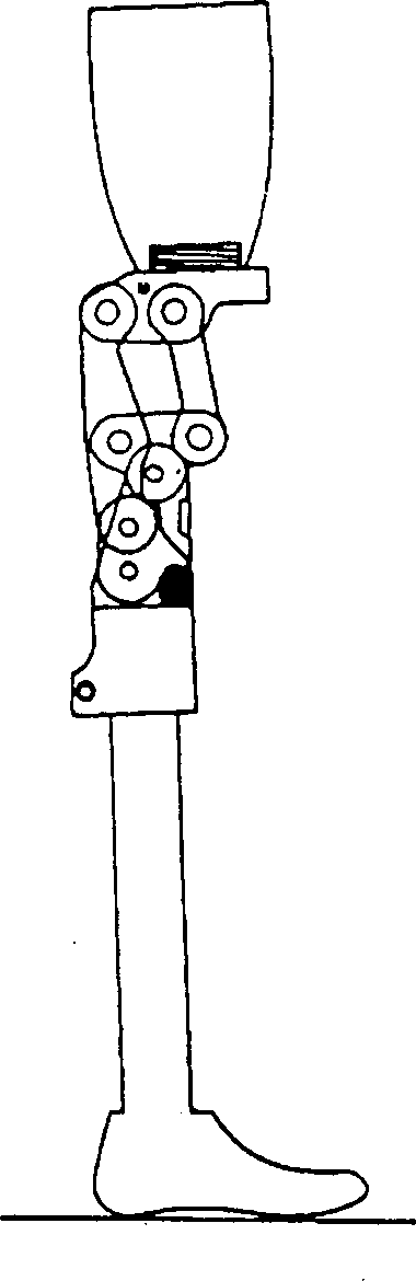
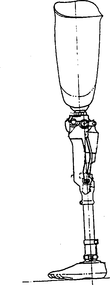
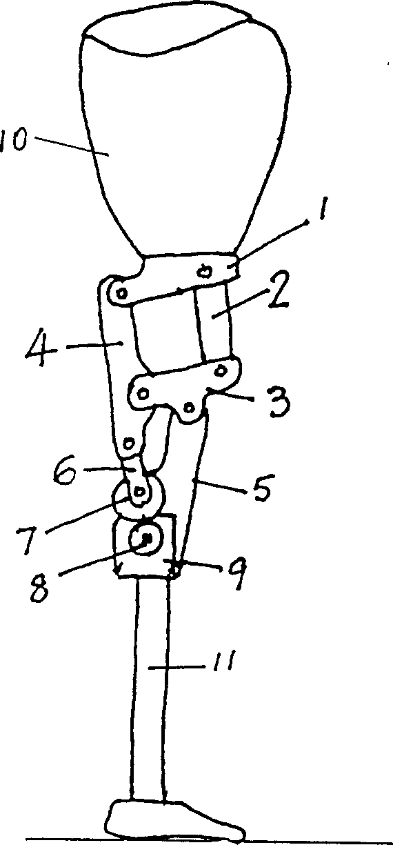
[0024] The specific structure and best implementation mode of the present invention will be described in detail below in conjunction with the accompanying drawings. image 3 , Figure 4 They are respectively the position of the knee joint mechanism of the present invention in the lower limb prosthesis and the variable schematic diagrams when the mechanism is optimally designed. The six-bar mechanism consists of component 1 (AB), component 2 (BD), component 3, (CDG), component 4 (ACE), component 5 (GF) and component 6 (EF). A~G are the seven hinge axes of the six-bar mechanism.

[0025] The thigh bar 10 is fixedly connected to the member 1, and the calf bar 11 is fixedly connected to the member 5. When the big and small legs are parallel ( image 3 ), the mechanism can be self-locking and has reliable stability.

[0026] l 1 ~ l 10 Respectively represent the rod length of the six-bar mechanism.

[0027] l 11 : The distance between the consolidation point I of thigh bar ...


PUM


Abstract

The present invention relates to structural design of six pole mechanism knee joint with knee moment of force controlling device, it is characterized in that a knee moment of force controlling device is set on the hinge shaft of member (5) and (6), said device is composed of step-by-step motor, driving gear wheel on the motor shaft and controllable friction moment of force system, said system adopts left and right symmetrical structure with central line as axle, and said structure mainly includes screw with left and right helix at two ends, left and right spiral nuts, compression spring and friction conical body set on screw, the friction conical body is fixed with member (6), its external conical surface and internal conical surface of member (5) form conical surface friction. Advantages flexible in operation, good controllability etc.

Description

technical field [0001] The invention relates to the design of a human prosthesis in hygiene, in particular to the structural design of a six-bar mechanism knee joint with a knee moment control device. Background technique [0002] Knee joint is an important part to realize the function of lower limb prosthesis. After wearing, the patient should try to keep the safety and close to the natural gait. To this end, it is necessary to meet the two basic requirements of stability in the support period and motion law in the swing period. There are three main methods to achieve the stability of the prosthetic limb during the support period: 1) installing a braking or locking device; 2) adjusting the alignment; 3) relying on the muscle strength of the residual limb. In order to realize the law of motion in the swing period, it depends on the rational design of the knee joint mechanism and the technology of controlling the knee moment. In the design of the mechanism, it is necessary...

Claims


Application Information

Patent Timeline
Patent Type & Authority Patents(China)
IPC IPC(8): A61F2/64
Inventor 金德闻张瑞红张济川王人成
Owner TSINGHUA UNIV
Why Eureka
Try Eureka