Fuel box fixing structure for small ships

A technology for fuel tanks and boats, which is applied in the field of fixed structure of fuel tanks, and can solve problems such as inability to position and fix in a stable state

Inactive Publication Date: 2004-12-08
HONDA MOTOR CO LTD
View PDF2 Cites 1 Cited by
  • Summary
  • Abstract
  • Description
  • Claims
  • Application Information

AI Technical Summary

Problems solved by technology

[0007] these questions, in Figure 9 The same happens in the shown structure, the box 6 is smaller than the specified size, and there is a gap between the smaller box and the inner wall side 8, 8, which cannot be fixed in a stable state; conversely, when the size of the box 6 is larger than the specified size, it becomes larger The box is pressed against the side of the inner wall with more pressure than necessary, and the box produces unnecessary stress

Method used


Image

  • Fuel box fixing structure for small ships
  • Fuel box fixing structure for small ships
  • Fuel box fixing structure for small ships

Examples


Embodiment Construction

[0027] specific implementation plan

[0028] Embodiments of the present invention will be described below with reference to the drawings.

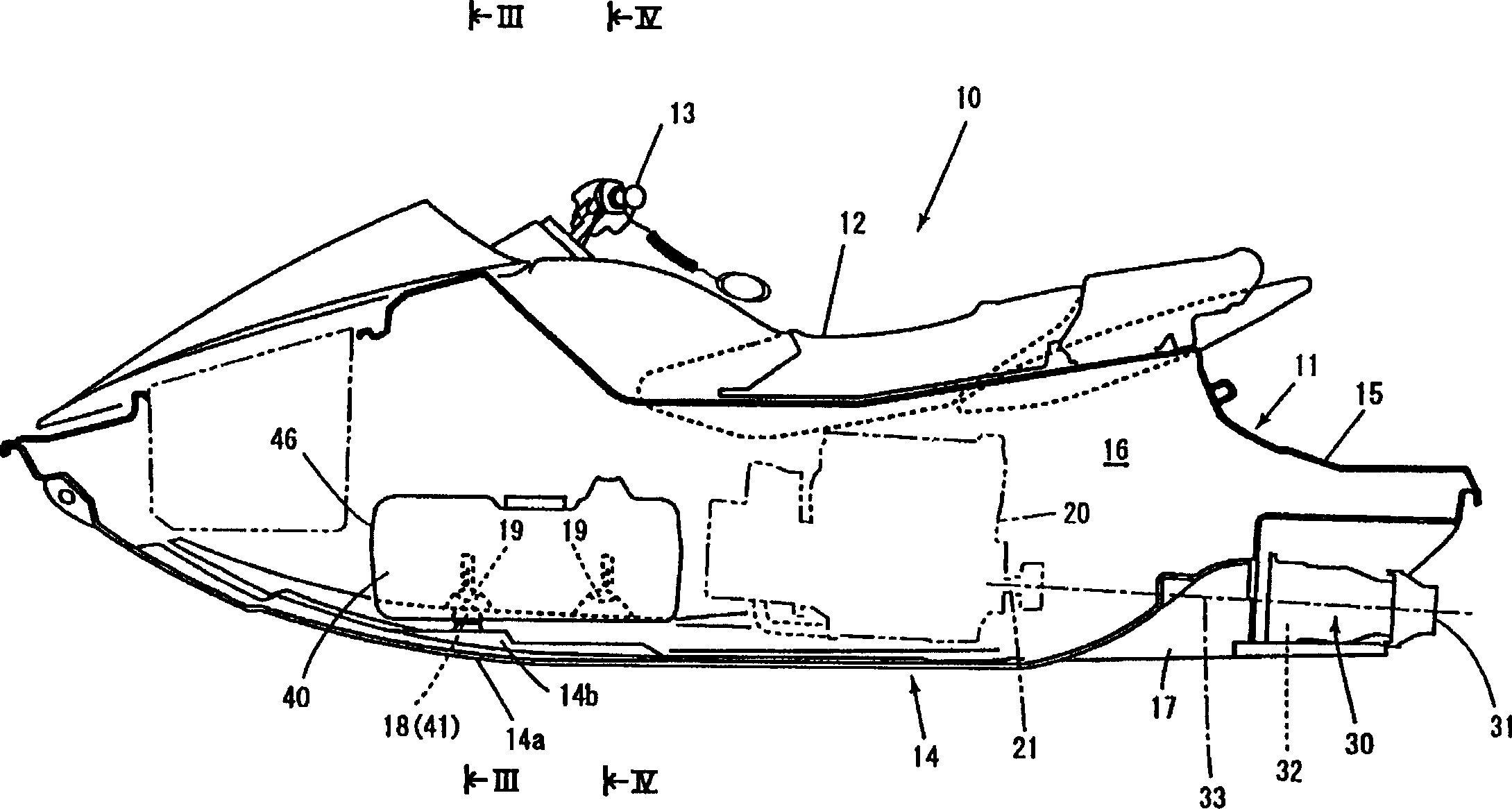
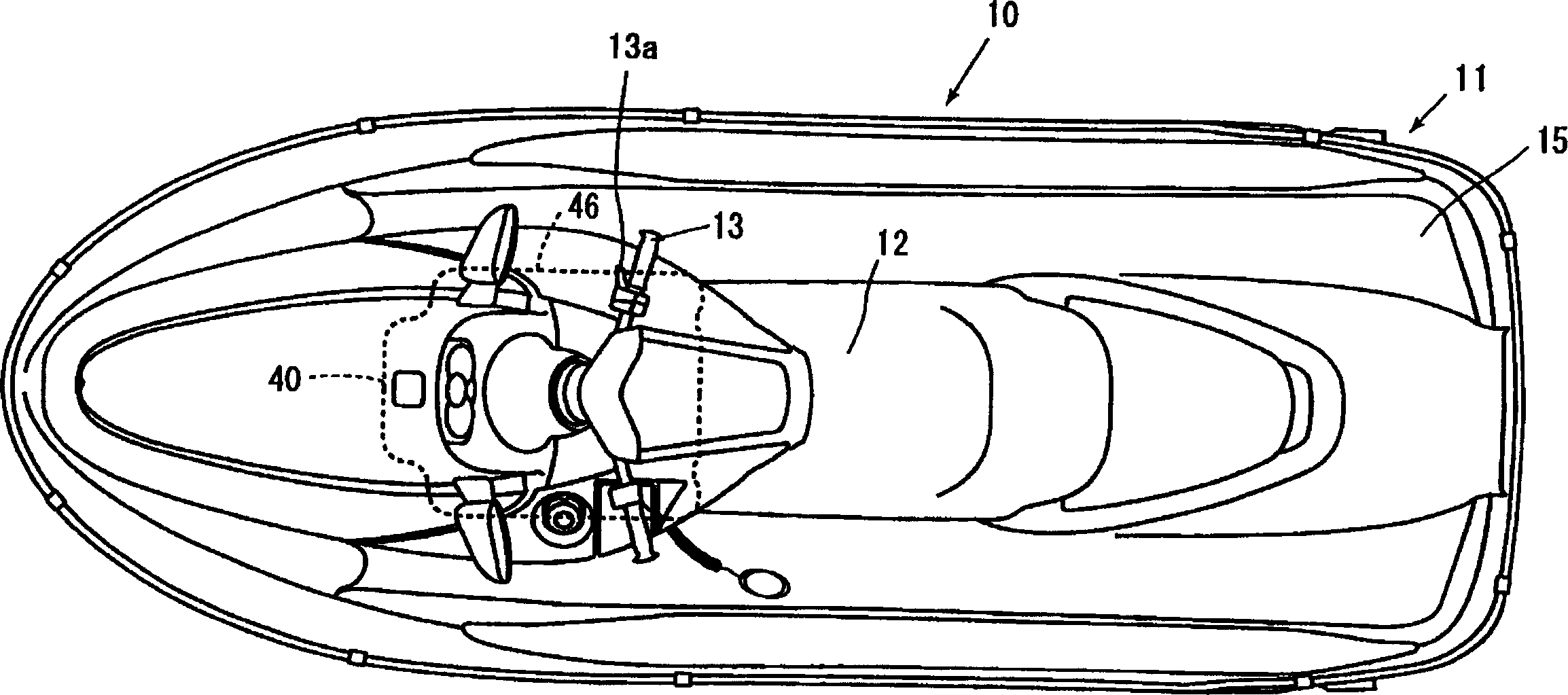
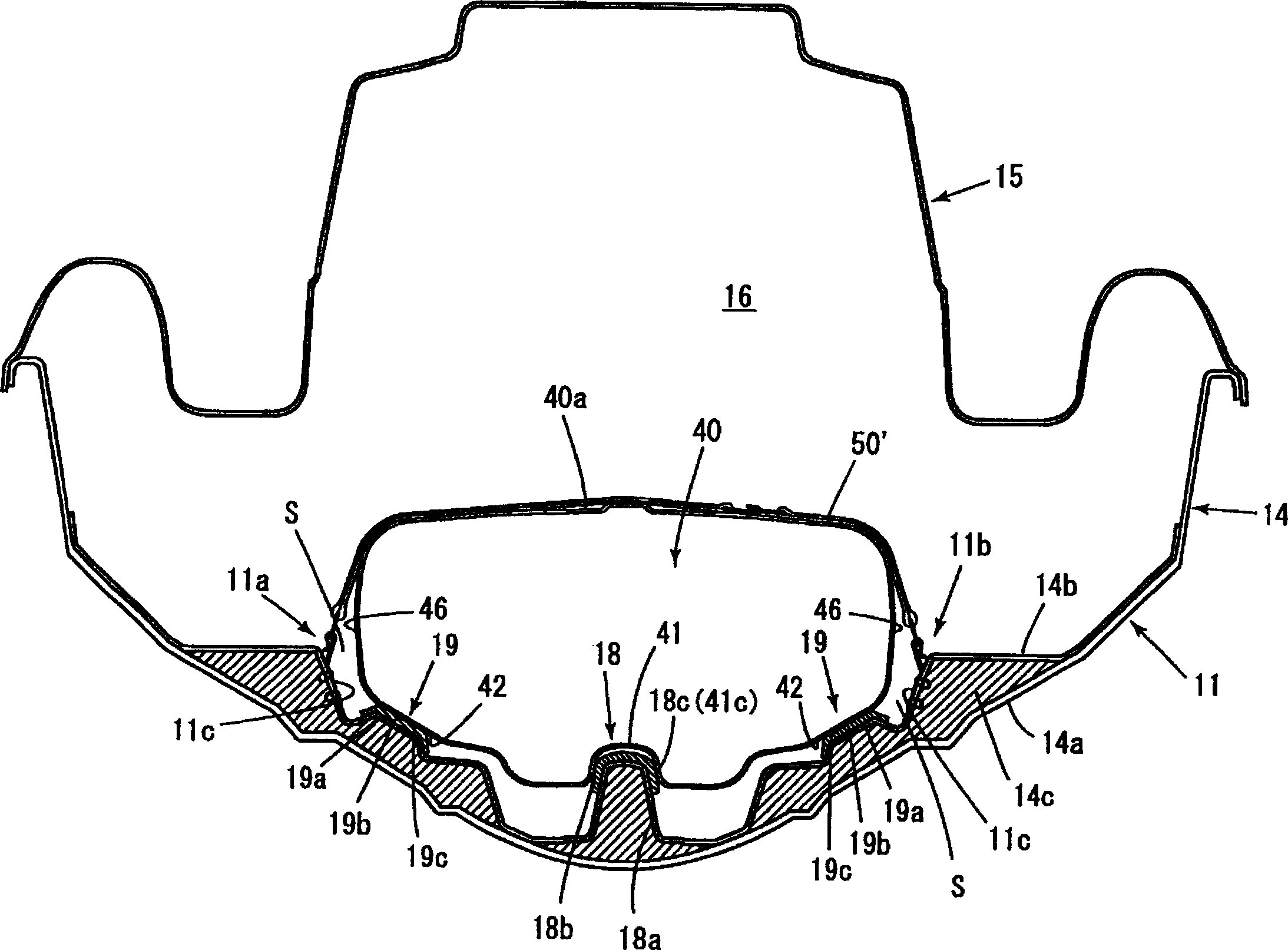
[0029] figure 1 It is a partially omitted side view showing an example of a small watercraft employing an embodiment of the fuel tank fixing structure of the present invention; figure 2 is the same figure 1 floor plan. image 3 yes figure 1 Part III-III cross-sectional view is omitted; Figure 4 yes figure 1 Part IV-IV sectional view is omitted; Figure 5 It is a schematic perspective view of the fuel tank mounted part at the bottom of the inner wall of the hull; Figure 6 is the bottom view of the fuel tank.

[0030] As shown in these figures (mainly figure 1 ), the small boat 10 of this embodiment is a saddle type small boat, and the occupant sits on the seat 12 on the hull 11 and can hold the belt adjustment rod 13a (refer to figure 2 ) of the steering handle 13 to operate.

[0031] The hull 11 is a floating body struc...


PUM


Abstract

The object of the present invention is to position and fix a fuel tank in a stable state and to prevent an unnecessary stress form being generated in the tank. A single projecting tapered portion for positioning 18 is formed on the bottom portion of the inner wall of a hull, and a single depressed portion for positioning 41, which is tapered in the same direction of the projecting portion 18 and is fitted on the projecting portion 18, is formed on the bottom portion of a fuel tank 40 mounted on the bottom portion of the hull, and a space S is formed, in a plan view, between the peripheral wall 46 of the fuel tank and the inner wall 11c of the hull. The fuel tank has a slanting surface 42 slanting nearly parallel to the slanting surface 19c of the inner wall of the bottom portion of the hull and the slanting surface 42 is supported movably in the direction along the slanting surface 42 by the projecting supporting portion 19 formed on the hull.

Description

technical field [0001] The present invention relates to a small boat, mainly relates to a fuel tank fixing structure of a saddle type small boat. Background technique [0002] In the prior art, as a small boat fuel tank fixed structure, such as Figure 8 In the structure shown in (a) (Japanese Patent Laying-Open No. 4-201797 ), a pair of tank supports 3,3 are set on the inner wall bottom 2 of the hull 1, and fuel tanks ( Hereinafter referred to as the box) 4, the box 4 is positioned at the bottom of the box 4 with the above-mentioned pair of box supporting parts 3 and 3, and the box 4 is fixed on the hull by the belt 5 hanging from the side of the hull through the box and hanging on the other side of the hull. superior. [0003] Additionally, if Figure 9 As shown, the box 6 is made into the shape suitable for the bottom 7 of the inner wall of the hull, and the box 6 is clamped by the opposite inner wall sides 8, 8 of the hull to fix it in position (Japanese Patent Laying-...

Claims


Application Information

Patent Timeline
Patent Type & Authority Patents(China)
IPC IPC(8): B63H11/04B63B25/08B63B25/24B63B35/73B63H21/00B63H21/38
CPCB63B35/731B63B2770/00B63B25/08B63B2025/087B63B25/24B63B17/0027B63B34/10
Inventor 长田直明
Owner HONDA MOTOR CO LTD
Why Eureka
Try Eureka