
A workpiece positioning device

A technology for positioning devices and workpieces, applied in auxiliary devices, manufacturing tools, metal processing equipment, etc., can solve problems such as increasing labor intensity of workers, increasing costs, and difficulty in unloading workpieces.

Active Publication Date: 2015-07-29
上海气焊机厂有限公司
View PDF7 Cites 0 Cited by
  • Summary
  • Abstract
  • Description
  • Claims
  • Application Information

AI Technical Summary

Problems solved by technology

[0002] At present, in welding production, for frame-type weldments, most positioning devices adopt the form of fixed positioning blocks or cylinder push-pull positioning blocks. Due to the deformation of the workpiece after welding, the use of fixed positioning blocks will make it difficult to unload the workpiece, which will greatly increase The labor intensity of workers and the reduction of production efficiency, although the push-pull positioning block of the cylinder solves the problem that the workpiece is difficult to unload, its cost is also greatly increased

Method used


Image

  • A workpiece positioning device

Examples


Embodiment Construction

[0015] The present invention will be further described below in conjunction with the accompanying drawings and embodiments.

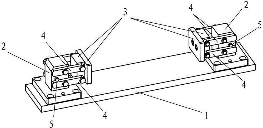
[0016] A workpiece positioning device, comprising a base 1 and two bases 2, the two bases 2 are fixed on the base 1 by bolts, the distance between the two bases 2 can be adjusted to the workpiece to be processed Fixed when matching the length. A positioning baffle 3 is respectively arranged on the opposite sides of the two bases 2, and the working surfaces of the two positioning baffles 3 are arranged oppositely;

[0017] Each of the left and right sides of each positioning baffle 3 is connected to the base 2 through two rocking arms 4 arranged in parallel up and down, and the rocking arms 4 are connected to the base 2 and the positioning baffle 3 respectively. Rotatably pivoted, the center distances of the two ends of the two rocker arms 4 are equal to each other, the distance between the centers of the two shafts on the positioning baffle 3 and the d...


PUM


Abstract

The invention discloses a workpiece positioning device which comprises a base and two pedestals, wherein a parallel four-rod mechanism is formed by the base, positioning baffles and two rocker arms on each side of each positioning baffle; and same parallel four-rod mechanisms are arranged on the left side and the right side of each positioning baffle in a matching manner, so that when the rocker arms rotate upwards, the positioning baffle can horizontally move upwards in a direction far away from the other pedestal in the manner of keeping an unchanged working surface direction. According to the workpiece positioning device, a principle of the parallel four-rod mechanism is skillfully used; when the rocker arms are arranged horizontally, a workpiece is just clamped; and when the rocker arms are in positions of fixed points, the workpiece can obtain a relatively stable positioning state. The workpiece is processed and deformed, and then is separated from a fixed point state, so that the workpiece can be detached naturally and easily. The workpiece positioning device is ingenious and reasonable in structure, the positioning and the assembly of the workpiece are facilitated, and the work efficiency is also greatly improved.

Description

technical field [0001] The invention relates to a positioning device, in particular to a positioning device suitable for welding a frame-type weldment. Background technique [0002] At present, in welding production, for frame-type weldments, most of the positioning devices adopt the form of fixed positioning blocks or cylinder push-pull positioning blocks. Due to the deformation of the workpiece after welding, the use of fixed positioning blocks will make it difficult to remove the workpiece, which will greatly increase Worker's labor intensity and reduce production efficiency, although the cylinder push-pull positioning block solves the problem that the workpiece is difficult to unload, its cost also increases greatly. Contents of the invention [0003] The technical problem to be solved by the present invention is to provide a workpiece positioning device with more reasonable structure, stable and reliable operation and lower cost. [0004] The technical scheme that th...

Claims


Application Information

Patent Timeline
Patent Type & Authority Patents(China)
IPC IPC(8): B23K37/04
Inventor 丁书才陈友虞
Owner 上海气焊机厂有限公司
Learn More