Power changing system for two-way changing between hydraulic energy and electric energy

A power distribution system and power technology, which is applied in the direction of auxiliary power equipment, control systems, power amplification, etc., can solve the problems of equipment costs, maintenance and repair costs and other adverse effects

Inactive Publication Date: 2005-01-19
戴姆勒-奔驰航天空中客车公司
View PDF0 Cites 3 Cited by
  • Summary
  • Abstract
  • Description
  • Claims
  • Application Information

AI Technical Summary

Problems solved by technology

This will have a negative impact on equipment costs and at the same time on the vehicle's own weight and additional costs (fuel consumption, maintenance and repair costs)
Another point to point out is that none of the system solutions described utilize bi-directional lateral feed solutions for hydraulic and electrical energy systems or are suggested to implement such a system solution

Method used


Image

  • Power changing system for two-way changing between hydraulic energy and electric energy
  • Power changing system for two-way changing between hydraulic energy and electric energy
  • Power changing system for two-way changing between hydraulic energy and electric energy

Examples


Embodiment Construction

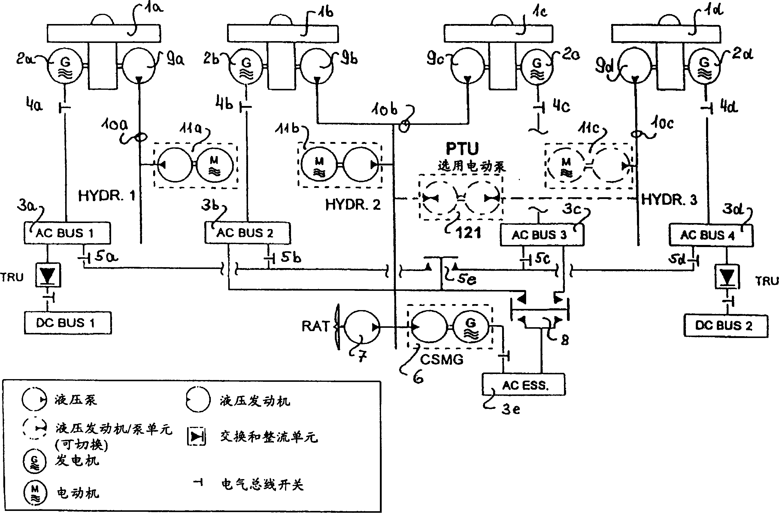
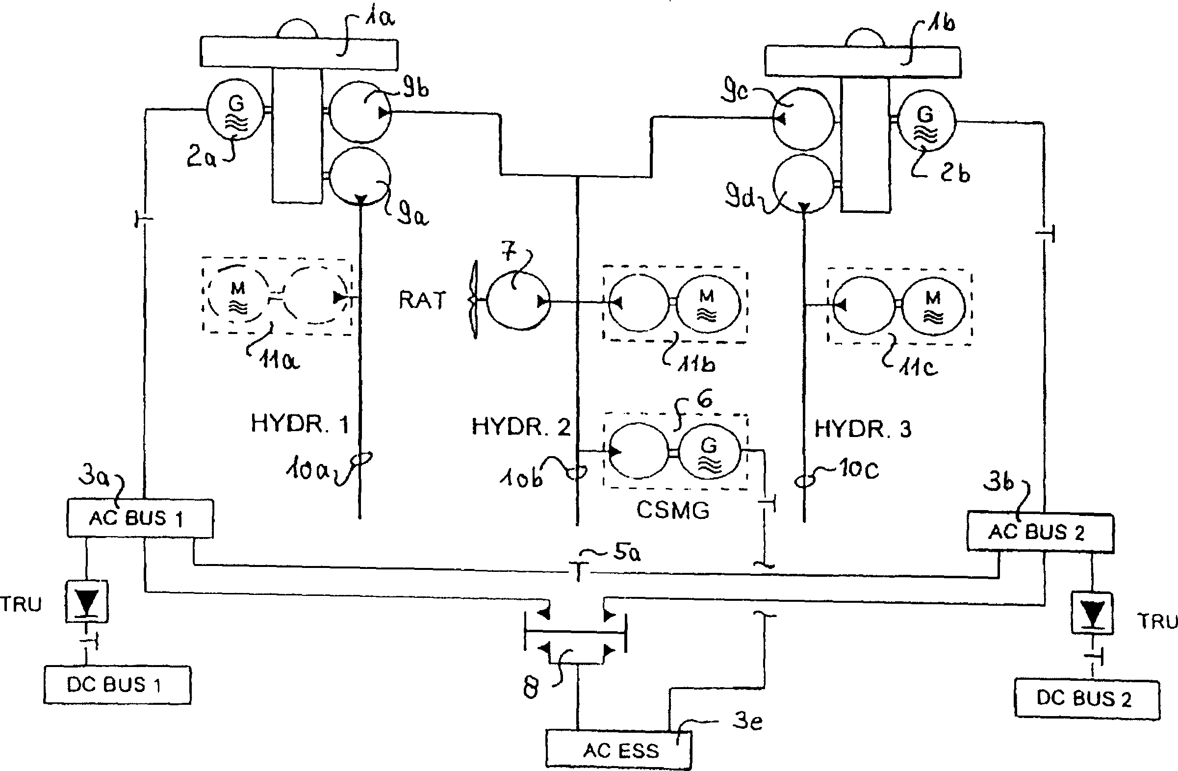
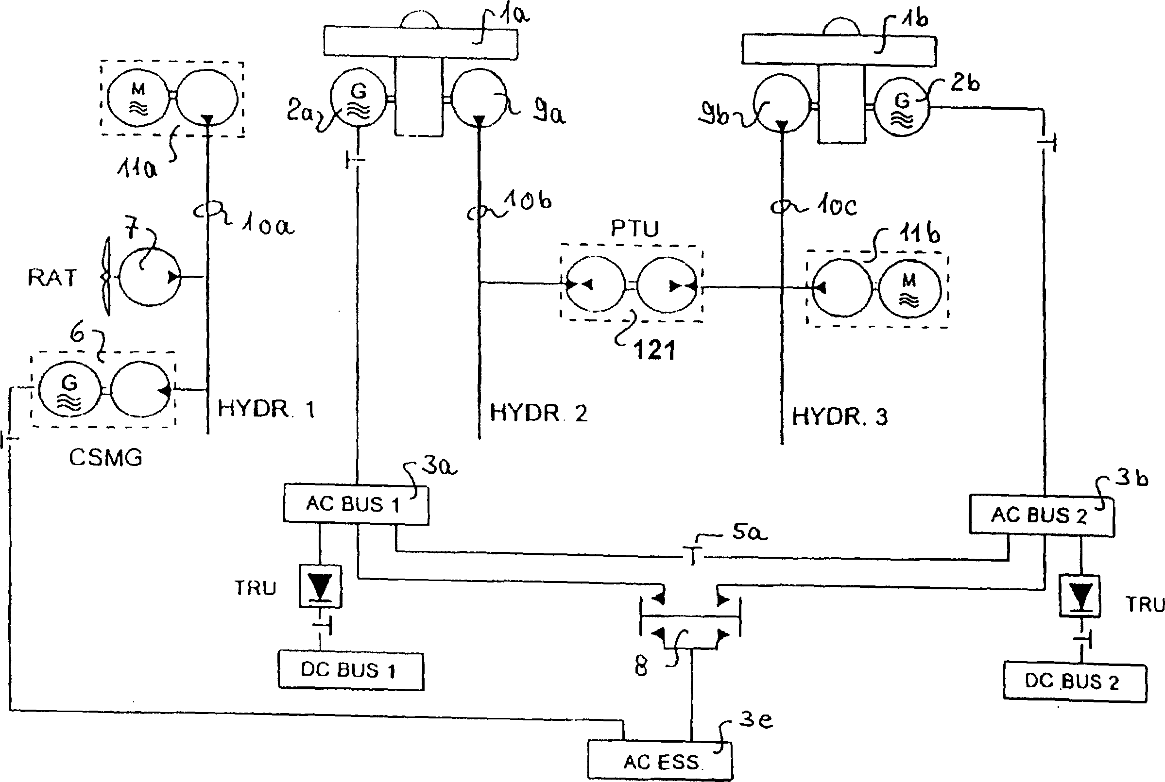
[0031] There is a known need on board aircraft for electrical and hydraulic emergency and backup energy sources, which are currently implemented with multiple installed energy converters (pumps, generators). Where an electrically driven hydraulic pump or a hydraulically driven emergency generator is used, said hydraulic pump or emergency generator constitutes a basis for Figures 1 to 3 part of the known (and described in the introductory part of this specification) system scheme. with the aircraft involved (such as figure 1 shown) four drive units and (such as figure 2 and 3 In contrast to the system solution of a typical hydraulic and electrical energy generation and supply system for the two drive units shown, a modification of the solution will be described below, which eliminates the accompanying (and has been criticized above) of the system solution. Shortcomings. Since the system solutions currently implemented on the aircraft have been quoted (detailed) descriptio...


PUM


Abstract

The invention provides a power transduction system used for bidirectional transduction between hydraulic energy and electrical energy. The invention selectively supplies energy transduced bidirectionally to an electric energy system or a hydraulic energy system mounted on a vehicle or a plane. By adopting the bidirectional power transduction system, few subsystems or functional systems are needed to achieve the known system scheme. The total installation power can be reduced by using the likelihood that hydraulic energy or electrical energy can be fed to related energy systems in the bidirection and transverse direction. In addition, the power and the energy of the vehicle or the plane can be managed and controlled as required; the manufacturing cost and the working cost of the energy of the machine can be reduced; the weight of the plane can be reduced.

Description

technical field [0001] The invention relates to a power conversion system for two-way conversion between hydraulic energy and electric energy of the energy system source of a motor vehicle, wherein different energy types are provided by using two-way conversion and selection to realize the electric energy system in the vehicle, preferably the aircraft. Energy supply for hydraulic energy systems. Background technique [0002] In the known on-vehicle (aircraft) energy systems of motor vehicles, the reliability of their work is largely guaranteed by the energy sources that work autonomously, and various energy systems installed in the system that play a key role in safety The consumers of the energy supply (output) are always available with hydraulic and / or electrical energy (power). These relate to hydraulic operating systems (installed on motor vehicles) (for motor vehicle control) and electrical / electronic systems, especially power plants and computer equipment (computers) ...

Claims


Application Information

Patent Timeline
Patent Type & Authority Patents(China)
IPC IPC(8): F03G7/00B64C13/42B64C13/50B64D27/00B64D41/00H02J3/46H02J4/00H02J9/06H02P9/04H02P29/00
CPCY02T50/44B64D41/00H02J4/00H02J2310/44Y02T50/40
Inventor 尤多·卡尔沃尔夫冈·贝斯宁斯蒂芬·弗里希麦尔
Owner 戴姆勒-奔驰航天空中客车公司
Why Eureka
Try Eureka