Machine for adhesive strip, process for adhesive strip in order to produce heat insulation and sealed wall and heat insulation and sealed wall

A technology for adhesive tapes, machines, applied in bulk goods, outer walls of container construction, adhesives, etc., which can solve problems such as tediousness, monotony, and surface irregularities

Inactive Publication Date: 2005-02-16
GAZTRANSPORT & TECHNIGAZ SA
View PDF2 Cites 4 Cited by
  • Summary
  • Abstract
  • Description
  • Claims
  • Application Information

AI Technical Summary

Problems solved by technology

This operation of manually securing the strip and the fact that the ends of the strip must overlap in the same slot results in some irregularities in the surface
Additionally, continuous second sealing barriers on the top and vertical walls of the container would be particularly tedious and tedious to perform

Method used


Image

  • Machine for adhesive strip, process for adhesive strip in order to produce heat insulation and sealed wall and heat insulation and sealed wall
  • Machine for adhesive strip, process for adhesive strip in order to produce heat insulation and sealed wall and heat insulation and sealed wall
  • Machine for adhesive strip, process for adhesive strip in order to produce heat insulation and sealed wall and heat insulation and sealed wall

Examples


Embodiment Construction

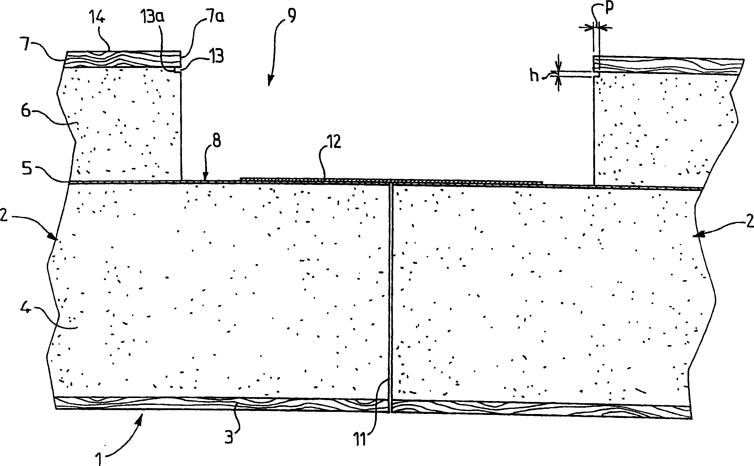
[0047] according to figure 1 , the thermally insulating and sealing wall 1 is formed by a wall panel indicated as a whole by the reference numeral 2, this wall 1 constituting a first thermally insulating barrier, a second thermally insulating barrier and a second sealing barrier. Each wall is substantially in the shape of a right-angled parallelepiped and consists of a first plywood 3 on which a first thermal insulation layer 4 is arranged, on which a layer of rigid or flexible slats 5; Subparts 6, 7 constitute a first insulating barrier part that is rectangular in plan view, with sides parallel to the sides of subparts 3, 4, 5; A rectangle with the same center, a peripheral side edge 8 of fixed length surrounds the subparts 6, 7 and is formed by the edges of the subparts 3, 4, 5. The subcomponents 3, 4 constitute a second insulating barrier part. The strip 5 covering the subcomponents 3, 4 constitutes a second sealing barrier part.

[0048] The panel 2 just described may ...


PUM

PropertyMeasurementUnit
thicknessaaaaaaaaaa
thicknessaaaaaaaaaa

Abstract

Two sections (2) which are to be glued together are laid next to each other transversely on a machine. The chassis (21) of the machine (20) carries means of supporting the band; means of pressing against the side of the band that is not glued to apply it to a surface between the means of support and a heater (30) to activate the glue. A continuous process of sticking together a band to form a watertight and insulating wall, using rectangular panels containing layers of impermeable material. Two adjacent panels are stuck together using a flexible band containing at least one fine metallic layer by continuous application of polymerizable or thermofusible glue to the band or the panels; continuous pressing of the band against the adjacent edges and continuous heating of the band in contact to activate the glue, before or after the pressing action. In addition a final cooling stage solidifies the glue. The glue can be applied to the band as it is stuck to the panels, or if thermofusible glue is used, it can be applied at a temperature at which it is fluid, before the band is cooled and wound onto a bobbin. The band can then be unrolled, heated to a second temperature less than or equal to the first to reactivate the glue as it is pressed continuously onto the panel edges. Independent claims are included for; (1) The machine (20) has a tubular chassis (21) with at least two longitudinal elements (22) connected to each other by at least one transverse element (23, 24). Rollers (26) are connected to the chassis along its longitudinal axis (L) so they roll against the surface (14) of two sections (2) which are to be glued together. The band is held by at least two longitudinal retaining pieces parallel to the axis of rotation of the rollers, with the active parts of the retaining pieces extending transversely outside the machine. The machine is automobile, with the chassis including a drive motor (84). The drive mechanism includes rollers (85) placed along the longitudinal axis near the means holding the band, with the rollers driven in rotation by the drive motor about an axis of rotation perpendicular to that of the rollers (26). The drive rollers can be moved between an active position against the walls (10) and a retracted position away from the walls. This movement is controlled by engaging and disengaging with longitudinal grooves (13). The heater is placed between the longitudinal elements, where the band is received, so it can heat the band using at least one resistance (32) and a ventilation system (33) which blows air across the resistance to form a flow of hot air towards the band. The heater can be placed upstream of the glue applicator (68) to speed the polymerisation of the glue. In this case, the heater is a temperature-controlled hot iron. Glue is applied to one side of the band (8) between the longitudinal elements. The band is held by a pressing roller whose distance in plan from the chassis is variable and which is designed to press the band against the glued surface. Coolers are mounted on the chassis between the longitudinal elements downstream of the heaters and glue application to accelerate the curing process; and (2) Insulating and watertight wall made using this process and / or machine.

Description

technical field [0001] The invention relates to a machine for bonding strips, a process for bonding strips in order to produce a thermally insulating and sealing wall and a thermally insulating and sealing wall, in particular to a system for installation in transport equipment, especially marine liquefied gas Insulated and sealed walls of vessels in the hull of a ship. Background technique [0002] Containers with two consecutive sealing barriers are known in particular from French patent application 2724623, wherein a first barrier is in contact with the product contained in the container, and an additional second barrier is placed between the first barrier and the transport. Between the devices, the two hermetic barriers are separated by two thermally insulating barriers. The container is formed by a thermally insulating and airtight wall consisting of a plurality of prefabricated substantially parallelepipedal panels, each comprising firstly a rigid plate with a layer of...

Claims


Application Information

Patent Timeline
Patent Type & Authority Patents(China)
IPC IPC(8): B63B3/68B29C65/00B29C65/10B29C65/50B63B25/16B65H37/04C09J5/00F17C13/00
CPCB29C66/1122B29K2995/0069B29C66/43B29C66/91421B29C65/5014B29C65/5021F17C13/004B29C65/5042B63B25/16B29C65/5092B29C65/4815B29C65/10B29C65/4835B29K2995/0015B29C66/1142B29C66/0342B29C66/72321B29C66/7234B29C66/8242B29C66/8362F17C2203/03F17C2205/00F17C2209/227
Inventor 马赛尔·尼亚斯克洛德·德利奥特
Owner GAZTRANSPORT & TECHNIGAZ SA
Why Eureka
Try Eureka