Supercharge Your Innovation With Domain-Expert AI Agents!

Metal mold device, electronic device and casing of electronic device making method

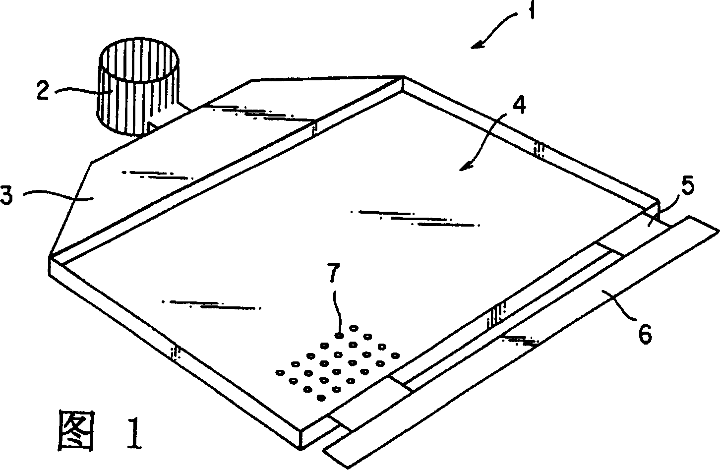
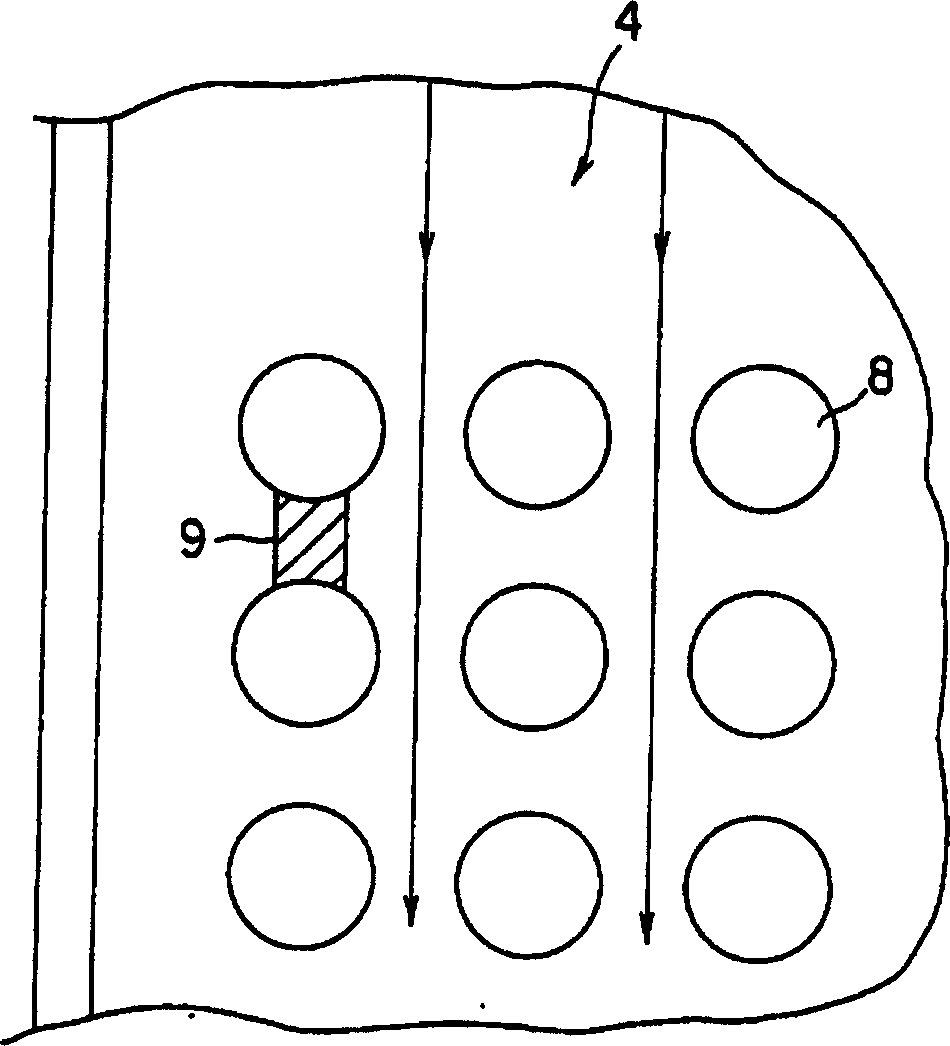
A metal mold and shell technology, which is applied in the direction of manufacturing tools, metal processing equipment, casting and molding equipment, etc., can solve the problems of large unfilled parts and inability to form holes 7, etc.

Inactive Publication Date: 2005-02-23
KK TOSHIBA +1
View PDF0 Cites 0 Cited by
  • Summary
  • Abstract
  • Description
  • Claims
  • Application Information

AI Technical Summary

Problems solved by technology

[0010] Therefore, the molten metal does not enter the portion between the pin members 8 to form an unfilled portion. In this way, the predetermined array of holes 7 cannot be formed, resulting in a large unfilled portion.

Method used


Image

  • Metal mold device, electronic device and casing of electronic device making method
  • Metal mold device, electronic device and casing of electronic device making method
  • Metal mold device, electronic device and casing of electronic device making method

Examples


Embodiment Construction

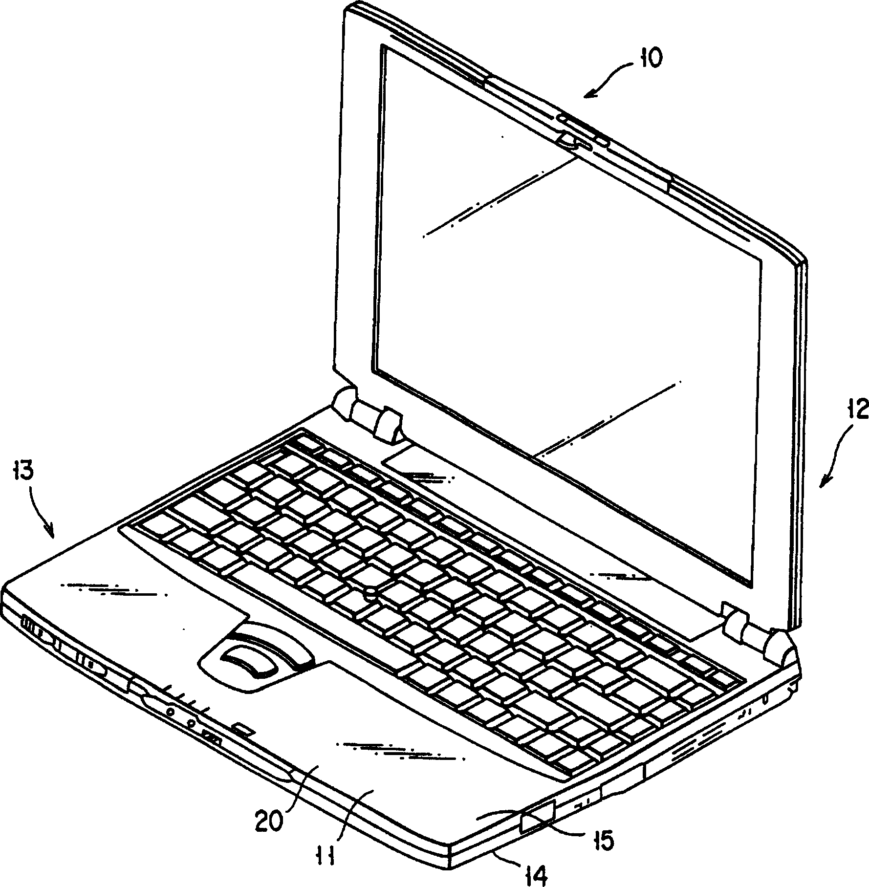
[0023] Below, refer to image 3 Turning to FIG. 8, an embodiment of the present invention is described.

[0024] image 3 It is an external view showing the shape of a portable computer 10 such as a notebook computer. In this figure, a portable computer 10 includes a computer body 11 and a display 12 rotatably supported by the computer body 11 . The computer body 11 is provided with a casing 13 . The case 13 is formed by connecting the lower case 14 and the upper case 15 with screws, for example. However, the joint structure of the lower case 14 and the upper case is not limited to this, and other joint structures may be used.

[0025] In the following description, a housing suitable for electronic equipment such as the portable computer 10 will be described as the housing 20 for electronic equipment. Below, refer to Figure 4 to Figure 8 for illustration.

[0026] For example, a case 20 for an electronic device such as a computer made of a light metal made of a magnesi...


PUM


Abstract

The invention provides a metal case (20) having regular perforations (21) for an electronic device, a metal mold (30) includes pins (36) provided on its cope (31) or drag (32). The pins (36) are arranged in such a manner that the center line connecting two adjacent pins is not perpendicular to the flow of molten metal that is introduced through a cavity (35) in the metal mold (30).

Description

technical field [0001] The present invention relates to the structure of a housing for electronic equipment made of light metal such as a computer, a method for manufacturing the housing for electronic equipment, and a mold device. Background technique [0002] Light metal housings for electronic equipment are currently mainly made of magnesium alloys. These alloys are formed by die casting or thixomelting. Although the device structures of these forming methods are different, the forming conditions are to inject the alloy melted to 580 to 750 degrees into a metal mold with a temperature of 100 to 350 degrees. [0003] FIG. 1 shows the structure of a conventional housing for electronic equipment. In this housing for electronic equipment, molten metal is introduced from the gate 2 which is a molten metal introduction portion of the metal mold device 1 (in this figure, a portion corresponding to the shape of the housing for electronic equipment immediately after molding is d...

Claims


Application Information

Patent Timeline
Patent Type & Authority Patents(China)
IPC IPC(8): B22D17/00B22C9/06B22D17/22
CPCB22C9/06
Inventor 细井隆高木伸行小野保夫木内干夫
Owner KK TOSHIBA
Features
  • R&D
  • Intellectual Property
  • Life Sciences
  • Materials
  • Tech Scout
  • Unparalleled Data Quality
  • Higher Quality Content
  • 60% Fewer Hallucinations
Learn More