Filter devece for clarifying contaminated liquids

A filter device, sewage technology, applied in the direction of filtration separation, mobile filter element filter, separation method, etc., can solve the problems of deterioration of filtration efficiency, high technical cost, etc.

Inactive Publication Date: 2005-03-02
HANS HUBER GMBH CO KG
View PDF2 Cites 0 Cited by
  • Summary
  • Abstract
  • Description
  • Claims
  • Application Information

AI Technical Summary

Problems solved by technology

Backwashing is closely associated with a rather high technical cost and also worsens the filtration efficiency

Method used


Image

  • Filter devece for clarifying contaminated liquids
  • Filter devece for clarifying contaminated liquids
  • Filter devece for clarifying contaminated liquids

Examples


Embodiment Construction

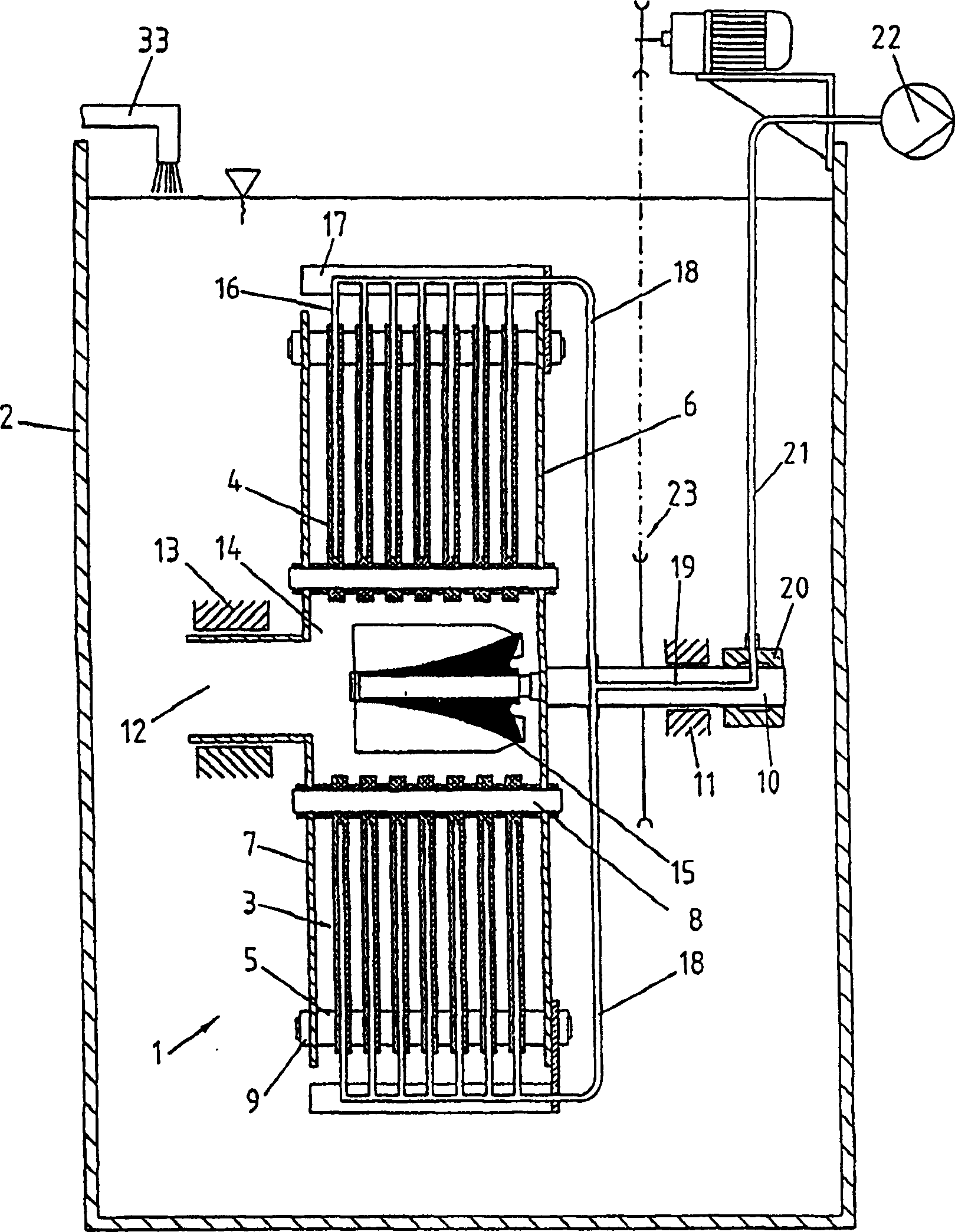
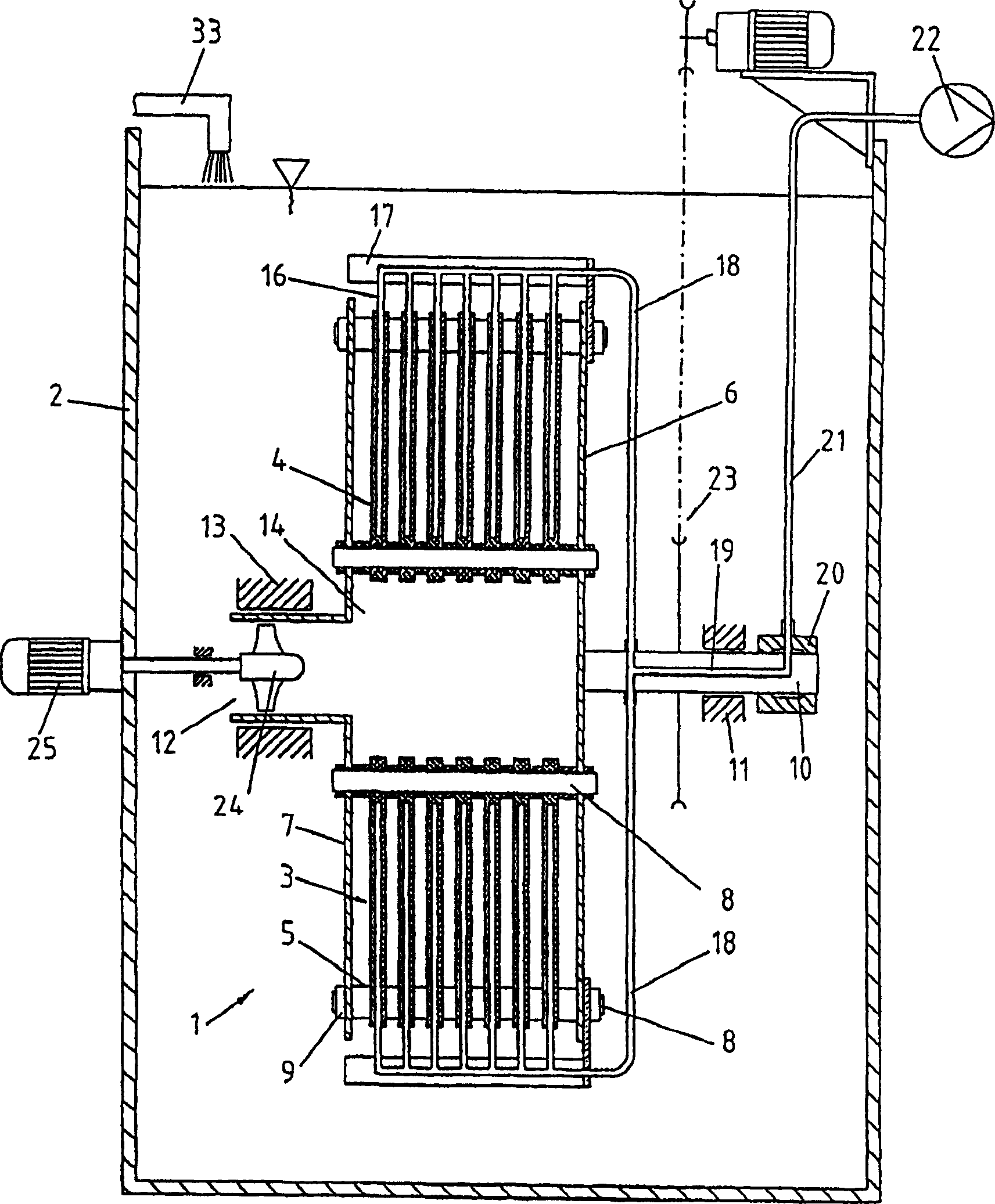
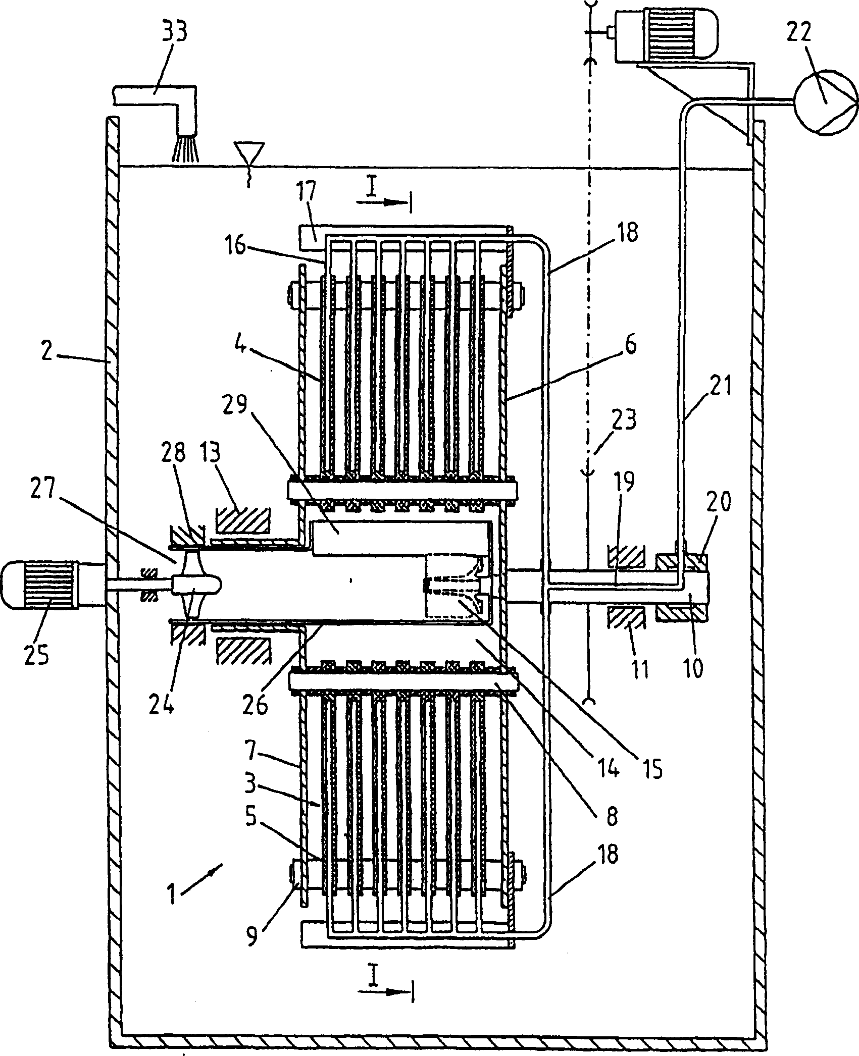
[0018] The filter device 1 is rotatably arranged in a container 2 containing a filter liquid. A plurality of filter assemblies 3 are arranged in a circle. The filter assembly 3 is composed of individual filter inserts 4 at a distance of preferably 4 to 8 mm. The filter insert 4, on the other hand, consists of known filter plates, not shown in the figures, through which the filtrate is discharged and which are provided with filters on both sides. The spacing between the filter elements 4 is ensured with spacers 5 . The filter assembly 3 is bounded on the one hand by a support plate 6 and on the other hand by a support flange 7 and is fastened with rods 8 and nuts 9 . The support disk 6 is fixedly connected to a drive shaft 10 and mounted rotatably in a bearing 11 . The support flange 7 has a suction opening 12 and is sucked into a seat 13 . The cavity 14 formed by the filter assembly 3 communicates through the suction hole 12 with the container 2 containing the filtered liq...


PUM


Abstract

Filtering device (1) consists of several filter elements (4) separated from each other which form filter modules (3) and are arrange in a container (2) containing contaminated liquid. The filter modules form a hollow chamber (14) which is connected to the container on one side via a suction opening and closed on the other side by a supporting plate (6). The hollow chamber interacts with a flow member. Preferred Features: The filter modules are supported on rods (8). The flow member is formed as a pump paddle wheel (15) and is connected to a drive shaft (10) via a supporting plate connected to the filter modules.

Description

technical field [0001] The invention relates to a filter device for sewage clarification, especially for waste water purification and water treatment. Background technique [0002] This type of filtering device is composed of many filter elements spaced apart at a certain distance, and these filter elements form a filter assembly and are arranged in a circular or polygonal shape in a container filled with filtered liquid to be rotatable. The filter element consists of a filter plate with filters on both sides and grooves to drain the filtrate. When the filter assembly starts to rotate, a flow resistance is generated on the filter area in the still static filtrate, which initially prevents the filtered material due to the high relative speed between the filter device and the liquid. Solids are deposited on the filter area. However, this initial flow resistance decreases with increasing rotation duration of the filter device because the filtered liquid circulates more and mo...

Claims


Application Information

Patent Timeline
Patent Type & Authority Patents(China)
IPC IPC(8): B01D33/00B01D33/21B01D35/26
CPCB01D35/26B01D33/21B01D33/39B01D33/68B01D33/06
Inventor E·哈姆斯M·格里戈
Owner HANS HUBER GMBH CO KG
Why Eureka
Try Eureka