Inner component of tower disc type catalytic cracking stripping equipment

A technology of catalytic cracking and internal components, applied in the direction of catalytic cracking, cracking, chemical instruments and methods, etc., can solve the problems of limiting the stripping effect, achieve the effect of strengthening the stripping effect, increasing the degree of movement, and simple structure

Inactive Publication Date: 2005-03-02
CHINA PETROLEUM & CHEM CORP +1
View PDF0 Cites 11 Cited by
  • Summary
  • Abstract
  • Description
  • Claims
  • Application Information

AI Technical Summary

Problems solved by technology

But its baffle stripper limits the further improvement of its stripping effect

Method used


Image

  • Inner component of tower disc type catalytic cracking stripping equipment
  • Inner component of tower disc type catalytic cracking stripping equipment
  • Inner component of tower disc type catalytic cracking stripping equipment

Examples


Embodiment

[0035] This example illustrates that the stripping efficiency of the stripper can be significantly improved by using the stripper internals provided by the present invention.

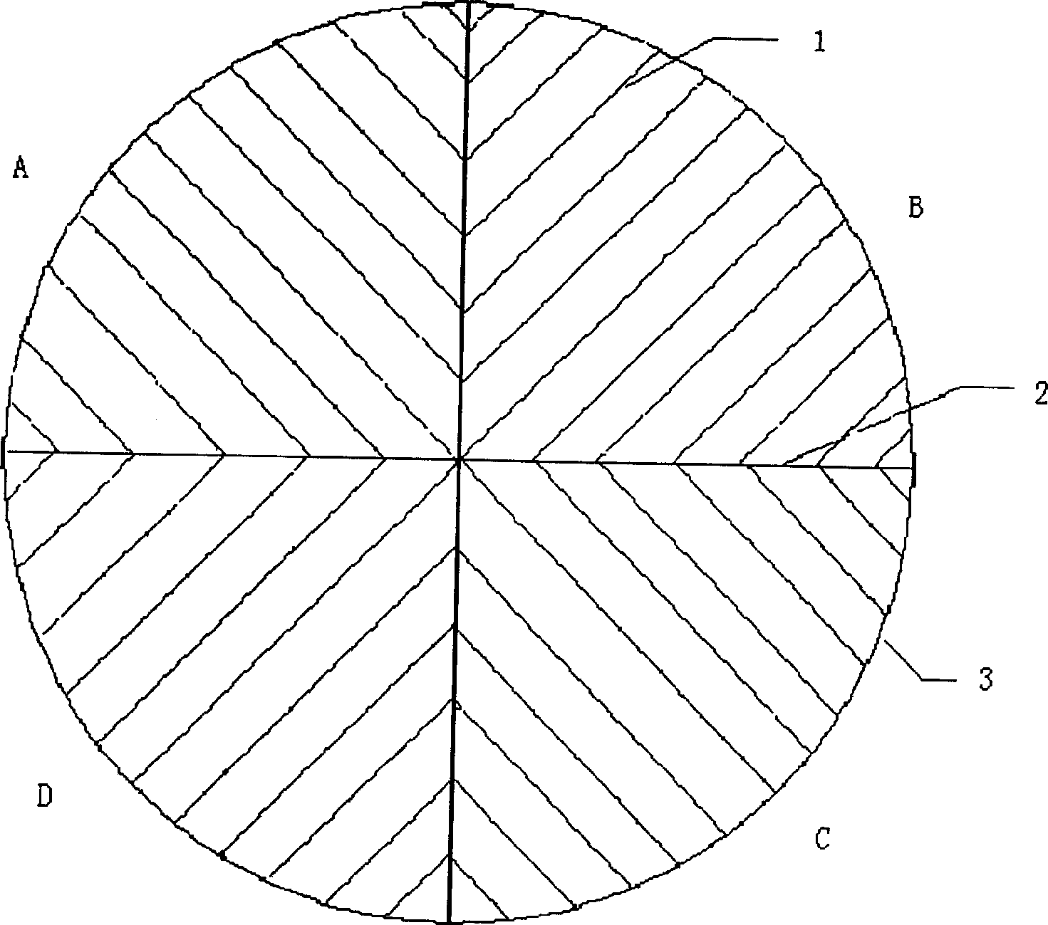
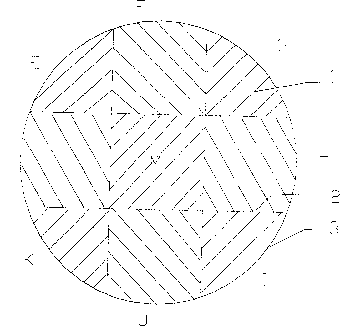
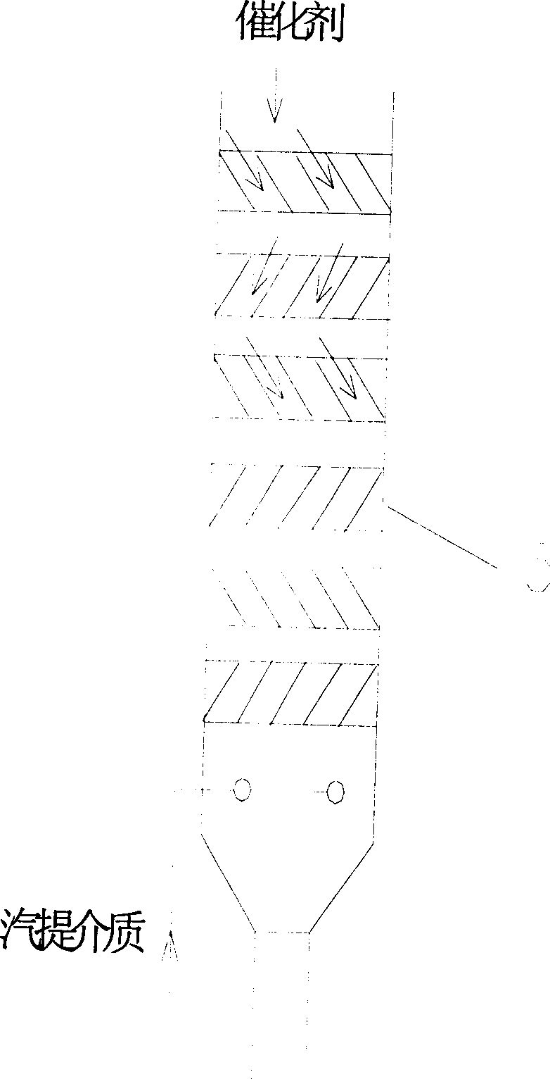
[0036] Transform the stripper of the medium-sized riser catalytic cracking unit, adopt the internal member of the present invention, the structure of the internal member is as follows figure 1shown. The inner diameter of the stripper is 500mm, and there are 4 internal components in the stripper. The height of the inner member is 100mm, and each inner member is divided into 4 zones, and the baffle sheet in each zone is 45° to the horizontal direction, and each inner member is placed horizontally from top to bottom along the axial direction, and makes the axial adjacent The inclination directions of the upper and lower corresponding baffle pieces in the inner member are different. If the upper layer is inclined clockwise, the lower layer is inclined counterclockwise, and vice versa. The interval between...


PUM

PropertyMeasurementUnit
porosityaaaaaaaaaa

Abstract

An inner member of a column-tray gas stripping machine mainly comprises two groups or more of baffles and vertical clapboards between each group of baffles. Each baffle comprises a group of baffles linked with the vertical clapboards and with the same tilting angles. The gas stripping rate by using the inner member could improve more than 20%.

Description

technical field [0001] The present invention pertains to catalytic cracking equipment for petroleum hydrocarbons in the absence of hydrogen, and more particularly to a catalytic cracking stripper internal. Background technique [0002] In the conventional catalytic cracking process, the raw oil is atomized with water vapor and sprayed into the riser, where it contacts the high-temperature catalyst (600-700°C) from the regenerator, and then vaporizes and reacts. The residence time of oil and gas in the riser is very short, generally only a few seconds. The reaction product is separated from the entrained catalyst by the cyclone separator and then leaves the reactor to the fractionation tower. The catalyst with coke (called spent catalyst) falls into the stripping section below from the settler. The stripping section is equipped with multi-layer herringbone baffles and superheated steam is introduced at the bottom, and the oil gas adsorbed on the catalyst to be used and the ...

Claims


Application Information

Patent Timeline
Patent Type & Authority Patents(China)
IPC IPC(8): B01J8/12C10G11/00
Inventor 朱丙田侯拴弟龙军许克家李松年钟孝湘何峻汪燮卿
Owner CHINA PETROLEUM & CHEM CORP
Why Eureka
Try Eureka